
Skin pulling device for slaughtering

A fixing device and wrapping technology, applied in slaughtering devices, slaughtering, slaughtering accessories, etc., can solve problems such as waste of labor, potential safety hazards, uneven force on the skin, etc., to save manual participation, increase buffering effect, and use convenient effect

Active Publication Date: 2019-01-04
内蒙古草原福美食品有限公司
View PDF11 Cites 5 Cited by
  • Summary
  • Abstract
  • Description
  • Claims
  • Application Information

AI Technical Summary

Problems solved by technology

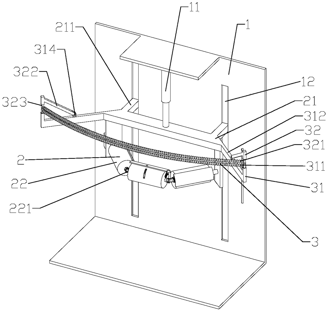
[0003] When pigs, cattle, sheep and other livestock are slaughtered, it is necessary to carry out skinning operations. The existing skinning equipment includes an operating table, a skinning device and a lifting cylinder, and the skin is connected to the skinning device through a chain. The skin is torn off from the animal carcass under the descending action of the lifting cylinder. However, since the skin is pulled by a chain connected to the skin, the force on the skin is uneven, resulting in asynchronous tearing of the skin and the carcass. On the same level, some places The skin has been torn off, but some places have not been torn off, so it is easy to tear the skin. Therefore, the existing skin pulling machine is accompanied by two workers manually peeling the livestock skin, which wastes labor and increases economic costs. The safety factor of vertical movement on the operating table is low, and there are great potential safety hazards. Therefore, a simple structure is designed, which can realize synchronous tearing on the same horizontal plane, evenly peeling, less personnel participation, and an automatic peeling device for slaughtering. Broad market prospects

Method used


Image

  • Skin pulling device for slaughtering
  • Skin pulling device for slaughtering
  • Skin pulling device for slaughtering

Examples


Embodiment Construction

[0032] In order to better understand the present invention, the implementation manner of the present invention will be explained in detail below in conjunction with the accompanying drawings.

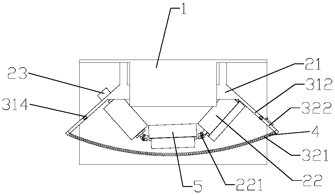
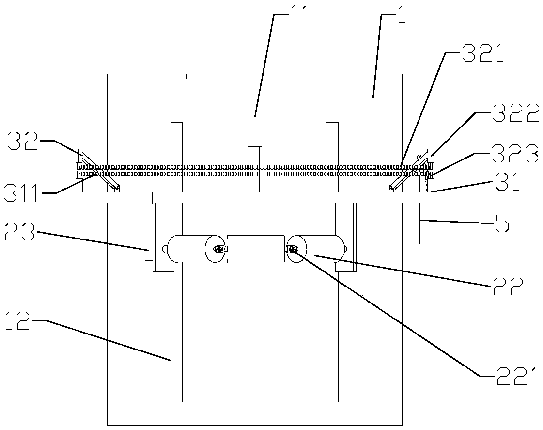
[0033] as attached figure 1 To attach Figure 13 As shown, the present invention includes an operating table 1, a skin rolling device 2 and a lifting cylinder 11, and the skin rolling device 2 includes a support frame 21, a reel 22 and a motor device 23, and the upper end of the support frame 21 is fixed to the piston rod of the lifting cylinder 11. Two sliding blocks 211 are extended at the front end of the support frame 21 , and the sliding blocks 211 are slidably arranged in the two vertical chute 12 of the console 1 . In order to make the livestock hide evenly stressed and avoid overlapping of the livestock hide, an arc-shaped leather supporting device 3 is arranged on the support frame 21. The leather supporting device 3 includes a supporting part 31, a pressing part 32 and a fixi...


PUM


Abstract

The invention discloses a skin pulling device for slaughtering. The skin pulling device comprises an operating table, a skin rolling device and a lifting cylinder, wherein an arc-shaped skin expandingdevice is arranged on the supporting frame, the skin expanding device comprises a supporting portion, a compressing portion and a fixing device, the supporting portion comprises a supporting rod andconnecting rods I arranged on both ends of the supporting rod and connected with the supporting frame, the compressing portion comprises a compressing rod and connecting rods II arranged on both endsof the compressing rod and hinged with the connecting rods I, the compressing rods correspond to the supporting rods in the vertical direction, and the compressing rods are arranged above the supporting rods; the fixing device is arranged at the right ends of the connecting rods I and the connecting rods II, and is used for fixing the connecting rods II rotated to certain positions. The skin pulling device can realize the effect of simultaneous downward tearing and pulling on the same horizontal plane, and is even in skin pulling without manual trimming and peeling.

Description

technical field [0001] The invention relates to a slaughtering device, in particular to a skin pulling device for slaughtering. Background technique [0002] At present, with the continuous improvement of living standards, people's demand for livestock is gradually increasing, making the number of livestock slaughtered more and more. Ordinary manual slaughter can no longer meet the needs of the society. Most of the livestock are transported to large-scale slaughter. Slaughtering is carried out in the field, and large-scale assembly line operations are adopted, which greatly improves the efficiency of slaughtering and ensures the hygiene and safety of livestock meat. [0003] When pigs, cattle, sheep and other livestock are slaughtered, it is necessary to carry out skinning operations. The existing skinning equipment includes an operating table, a skinning device and a lifting cylinder, and the skin is connected to the skinning device through a chain. The skin is torn off fr...

Claims


Application Information

Patent Timeline
Patent Type & Authority Applications(China)
IPC IPC(8): A22B5/16
CPCA22B5/161
Inventor 朱建玉刘子铭
Owner 内蒙古草原福美食品有限公司
Learn More