
Feed grinding device for animal husbandry

A grinding device and animal husbandry technology, applied in the field of animal husbandry machinery, can solve the problems of insufficient refinement of feed and poor grinding effect, and achieve the effects of improving feed grinding efficiency, ingenious structure and reasonable design

Inactive Publication Date: 2019-01-04
蒋洲琳
View PDF8 Cites 13 Cited by
  • Summary
  • Abstract
  • Description
  • Claims
  • Application Information

AI Technical Summary

Problems solved by technology

In order to ensure that the livestock can eat and digest the feed well, it is necessary to grind and refine the feed before feeding the livestock. However, the current grinding device does not have a good grinding effect on the feed and cannot achieve sufficient refinement of the feed. Therefore, At present, there is an urgent need for a feed grinding device for animal husbandry to solve the above technical problems

Method used


Image

  • Feed grinding device for animal husbandry
  • Feed grinding device for animal husbandry
  • Feed grinding device for animal husbandry

Examples


Embodiment 1

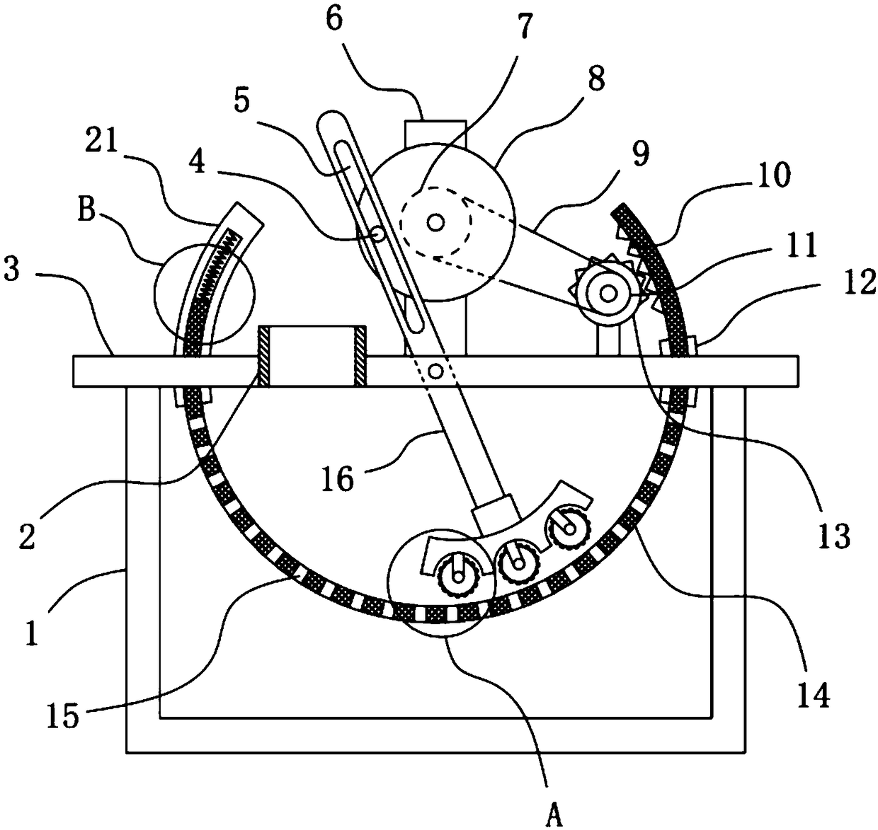
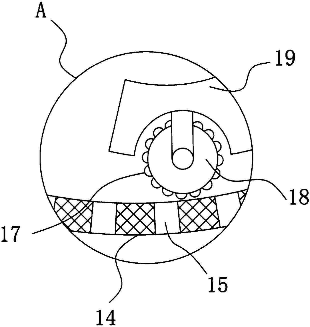
[0023] see Figure 1-2 , a feed grinding device for animal husbandry, comprising a collection box 1, a horizontal plate 3 is fixedly installed horizontally on the collection box 1, a support frame 6 is vertically fixedly installed on the horizontal plate 3, and a rotating type is installed on the support frame 6. The rotating disc 8 can be driven and rotated with an external drive motor, and the output shaft of the driving motor is coaxially fixed with the rotating disc 8 .

[0024] The front of the rotating disk 8 is coaxially fixed with a rotating disk 8, and the front of the rotating disk 8 is eccentrically fixed with a transmission pin 4. The horizontal plate 3 is rotatably provided with a rotating plate 16, and the rotating plate 16 is provided with a guide bar hole 5. The transmission pin shaft 4 slides through the guide bar hole 5 , and the transmission pin shaft 4 can slide along the guide bar hole 5 to realize the transmission effect on the rotating plate 16 .

[002...

Embodiment 2

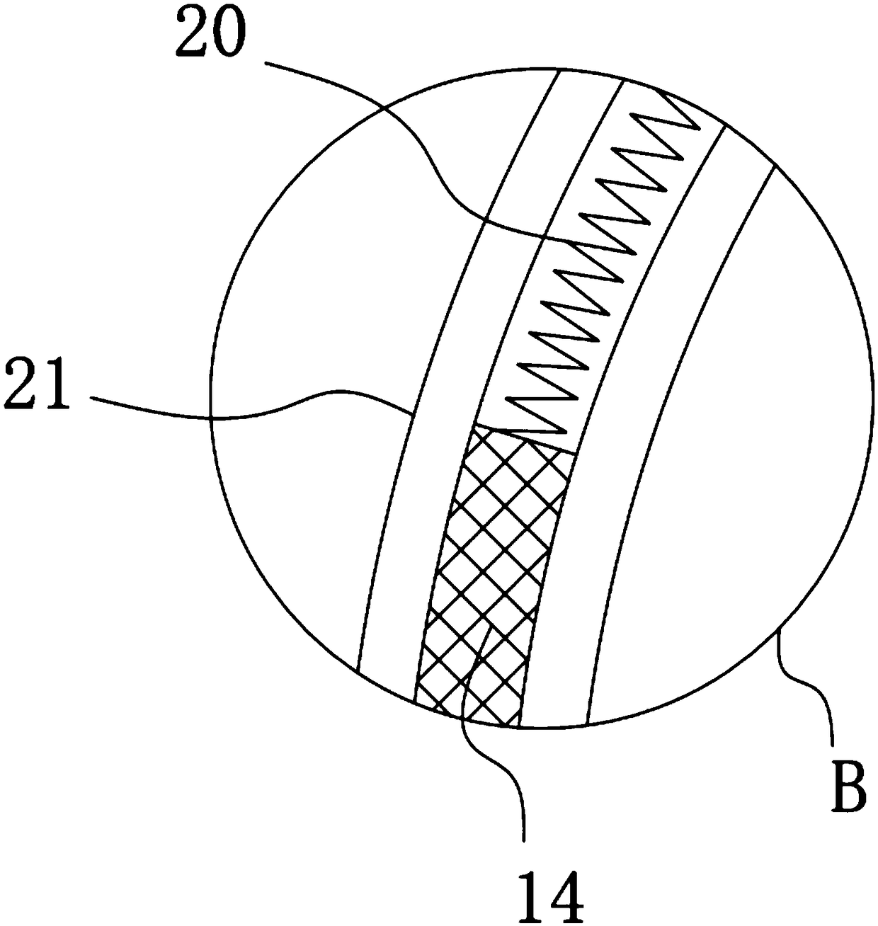
[0028] On the basis of Embodiment 1, in addition, the limit cover plate 21 and the limit arc plate 12 are fixedly installed on the horizontal plate 3, and the left end of the arc plate 14 is slidably embedded in the limit cover plate 21, and the arc plate 14 Sliding through the limiting arc plate 12, the inner rack 10 is fixedly installed on the inner wall of the inner rack 10, and the horizontal plate 3 is rotatably provided with an incomplete gear 13 that is in transmission engagement with the inner rack 10.

[0029] Further, the driving pulley 7 is coaxially fixedly installed on the back of the rotating disk 8, the driven pulley 11 is fixedly installed coaxially on the incomplete gear 13, and the driving belt 9 is sleeved on the driven pulley 11 and the driving pulley 7. .

[0030] The rotation of the rotating disk 8 drives the driving pulley 7 to rotate, and the driving pulley 7 drives the driven pulley 11 to rotate through the transmission belt 9, and the driven pulley 11...

Embodiment 3

[0033] On the basis of Example 2, such as Figure 4 As shown, in addition, the side wall hinge of the collection box 1 is connected with a dodge door 22, and the dodge door 22 is fixedly equipped with a connection ear 23, and the connection ear 23 is provided with a locking screw threaded with the collection box 1, and the feed grinding is completed. Finally, the dodge door 22 can be opened by removing the locking screw, and now the ground feed can be taken out from the collection box 1, and the operation process is simple and convenient.


PUM


Abstract

The invention discloses a feed grinding device for animal husbandry, and relates to the technical field of animal husbandry machinery. The device comprises a collecting box, a horizontal plate is horizontally and fixedly installed on the collecting box, a supporting frame is vertically and fixedly installed on the horizontal plate, a rotary disc is rotatably arranged on the supporting frame, a rotary plate is coaxially and fixedly installed on the front face of the rotary disc, a plurality of discharging holes are uniformly formed in an arc-shaped plate, an arc-shaped transmission frame is fixedly installed at the lower end of the rotary plate, and a plurality of grinding rollers abutting against the inner wall of the arc-shaped plate are rotatably installed on the bottom face of the arc-shaped transmission frame. The feed grinding device has the advantages of ingenious structure and reasonable design, the grinding rollers are driven by arc-shaped transmission frame to rotatably grindfeed on the arc-shaped plate due to the swinging of the rotary plate, the clockwise and counterclockwise rotation of the arc-shaped plate is achieved by the intermittent meshing of an incomplete gearand an inner rack under the elastic action of an restoring spring to allow the arc-shaped plate and the grinding rollers to perform thorough opposite movement, and therefore the feed grinding efficiency is greatly improved.

Description

technical field [0001] The invention relates to the technical field of animal husbandry machinery, in particular to a feed grinding device for animal husbandry. Background technique [0002] Animal husbandry is the use of livestock and poultry and other animals that have been domesticated by humans, or the physiological functions of wild animals such as deer, musk deer, fox, mink, otter, quail, etc., through artificial feeding and breeding, so that they can transform the energy of plants such as pasture and feed It is a production sector for animals to obtain livestock products such as meat, eggs, milk, wool, cashmere, hides, silk, and medicinal materials. It is different from self-sufficient livestock breeding. The main characteristics of animal husbandry are centralization, scale, and Profit is the purpose of production. Animal husbandry is an extremely important link in the exchange of materials between humans and nature. Animal husbandry is one of the components of agric...

Claims


Application Information

Patent Timeline
Patent Type & Authority Applications(China)
IPC IPC(8): B02C19/10B02C23/16A23N17/00
CPCA23N17/00B02C19/10B02C23/16B02C2023/165
Inventor 蒋洲琳
Owner 蒋洲琳
Learn More