Pipe Fitting Gluing Equipment

A technology for pipe fittings and gluing, which is applied to coatings and devices for coating liquid on the surface, etc., can solve the problems of unfavorable saving of production costs, waste of materials, complicated procedures, etc., and achieve cost saving, pollution reduction, and reduction of irritating odor Effect

Active Publication Date: 2020-08-21
廖维东
View PDF11 Cites 0 Cited by
  • Summary
  • Abstract
  • Description
  • Claims
  • Application Information

AI Technical Summary

Problems solved by technology

The plug-in glue application method needs to install a sleeve on the head of the pipe fitting (one end of the sleeve has an opening and the other end is closed) to prevent the glue from entering the inside of the pipe fitting. When the pipe fitting is inserted into the glue, the surface of the pipe fitting and the sleeve are covered with glue. After the pipe fittings are pulled out from the glue, the sleeves need to be pulled out from the pipe fittings. This method is not only cumbersome, but also the sleeves stuck to the glue cannot be reused, resulting in waste of materials and is not conducive to saving production costs.

Method used


Image

  • Pipe Fitting Gluing Equipment
  • Pipe Fitting Gluing Equipment
  • Pipe Fitting Gluing Equipment

Examples


Embodiment Construction

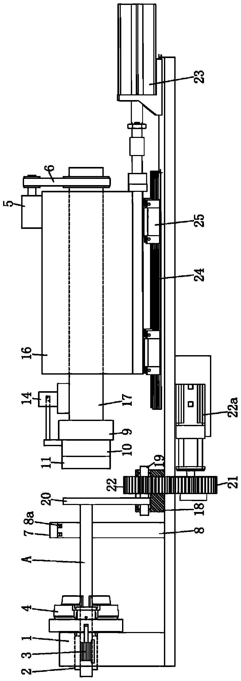
[0029] Such as figure 1 As shown, the pipe fitting gluing equipment of the present invention includes a support seat, a clamp, a first driving mechanism, a glue feeding mechanism, a gluing mechanism, a mounting seat, and a driving mechanism. Each part and the relationship between them will be described in detail below :

[0030] Such as figure 1 As shown, a first through hole is provided on the support base 1, and a guide sleeve 2 is installed in the first through hole. The function of 2 forms a supporting effect on one end of the pipe fitting A. The first through hole is a stepped hole, and one end of the guide sleeve 2 is limited by the step of the stepped hole, and the other end of the guide sleeve 2 is exposed outside the first through hole, so that when installing and dismounting the guide sleeve 2 It is very convenient, and through the position-limiting effect of the steps, when the pipe fitting A passes through the guide sleeve 2, the guide sleeve 2 will not move und...


PUM


Abstract

The invention discloses a gluing device for a pipe fitting, which comprises a supporting seat, wherein the supporting seat is provided with a first through hole; a clamp used for the pipe fitting to pass through and clamping the pipe fitting, wherein one end of the clamp is fixedly connected with the supporting seat, and a position of the clamp where the pipe fitting passes through corresponds tothe first through hole; a first driving mechanism connected with the clamp, wherein the first driving mechanism drives the clamp to contract radially so as to form a clamping action on the pipe fitting; a glue feeding mechanism for conveying the glue to the surface of a work piece; a mounting seat provided with a through hole, wherein a rotating shaft is arranged in the through hole, and two endsof the rotating shaft are respectively exposed outside the through hole; a gluing mechanism, wherein one end of the gluing mechanism is fixedly connected with one end of the rotating shaft; a drivingmechanism connected with the other end of the rotating shaft, wherein the driving mechanism drives the rotating shaft to rotate so as to brush the glue on the surface of the pipe fitting. The device facilitates reducing production cost.

Description

technical field [0001] The invention relates to the technical field of pipe fitting processing, in particular to a pipe fitting gluing equipment. Background technique [0002] At present, there are two ways of gluing pipe fittings: manual gluing and plug-in gluing. Among them, manual gluing is to use a tool such as a brush to brush on the surface of the pipe fittings, so that the glue is evenly coated on the surface of the pipe fittings. The characteristics of this method are: flexible operation, but in the actual production process, because the glue is applied with a small brush, it will drip to the ground continuously, and it will drip on the table and clothes if you are not careful, it is difficult to clean, and the benefit is low. Unable to improve. At the same time, the black glue used is easy to solidify. During use, it needs to be diluted with acetone every hour, and it needs to be stirred continuously. Acetone has strong volatility and irritating smell, and the wor...

Claims


Application Information

Patent Timeline
Patent Type & Authority Patents(China)
IPC IPC(8): B05C5/02B05C11/02B05C11/10B05C13/02
CPCB05C5/0208B05C11/021B05C11/1002B05C13/02
Inventor 廖维东
Owner 廖维东
Why Eureka
Try Eureka