
A track groove wall cleaning device

A cleaning device and track groove technology, applied in cleaning methods and appliances, cleaning methods using tools, chemical instruments and methods, etc., can solve problems such as inaccurate detection results and influence of detection results, and achieve wide application range and convenient use Effect

Inactive Publication Date: 2020-12-01
济南居翠教育科技有限公司
View PDF8 Cites 0 Cited by
  • Summary
  • Abstract
  • Description
  • Claims
  • Application Information

AI Technical Summary

Problems solved by technology

[0003] Aiming at the deficiencies of the prior art, the present invention provides a track groove wall cleaning device, which has the advantages of being able to remove the stains on the surface of the industrial track, making the parallelism detection results more accurate, etc. Therefore, when detecting the parallelism of industrial tracks, these granular stains can easily affect the detection results, resulting in inaccurate detection results

Method used


Image

  • A track groove wall cleaning device
  • A track groove wall cleaning device
  • A track groove wall cleaning device

Examples


Embodiment 1

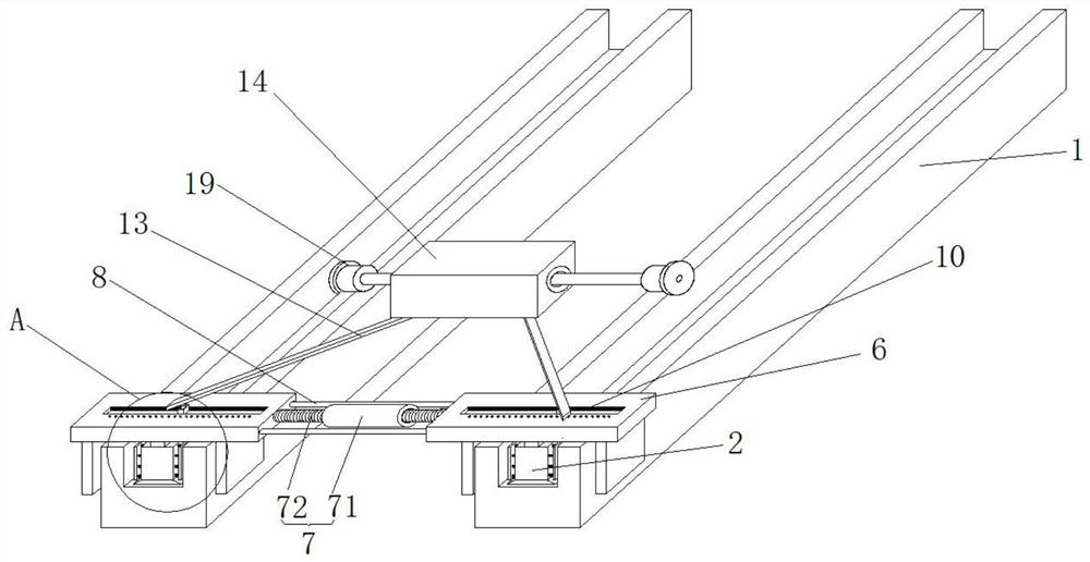
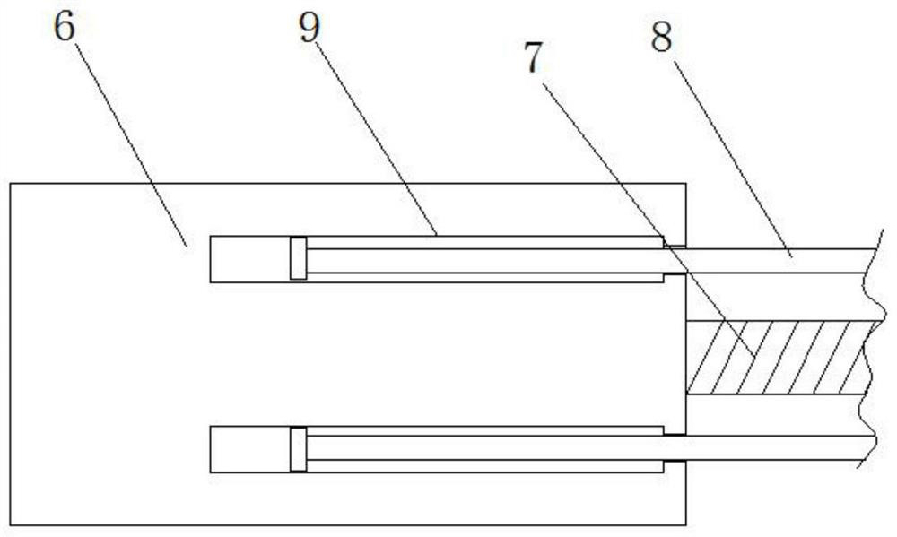
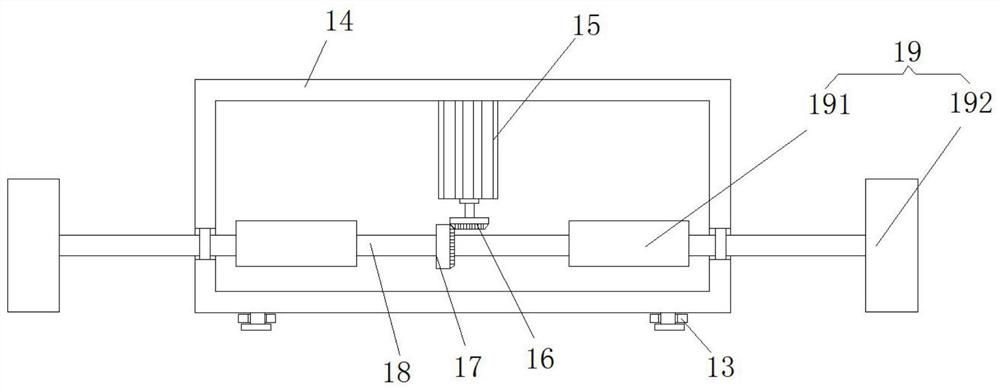
[0021] see Figure 1-4 , this embodiment provides a track groove wall cleaning device, including two track bodies 1, the inner walls of the two track bodies 1 are slidingly connected with brush blocks 2, and both sides of the brush block 2 are fixedly connected with springs 3. The end of the spring 3 away from the brush block 2 is fixedly connected to the brush plate 4, the bottom of the brush block 2 is fixedly connected to the scraper 5, and the tops of the two brush blocks 2 are fixedly connected to the mounting plate 6, and the two mounting plates 6 An adjustment assembly 7 is fixedly connected between the two mounting plates 6, and a limiting rod 8 is arranged between the two mounting plates 6. The opposite sides of the two mounting plates 6 are provided with a limiting groove 9, and the limiting rod 8 is movably connected with the limiting groove 9, and the limiting The position bar 8 is a T-shaped bar, and the top of the mounting plate 6 is provided with a convex groove...

Embodiment 2

[0024] see Figure 1-4 A further improvement is made on the basis of Example 1: the brush plate 4 is a plastic plate, and the side of the brush plate 4 away from the spring 3 is provided with a sponge, and the stain on the inner wall surface of the track body 1 can be effectively wiped by the sponge , and the cleaning effect is better, the adjustment assembly 7 includes a threaded sleeve 71, the two ends of the threaded sleeve 71 are threaded with a threaded rod 72, the threaded rod 72 is fixedly connected with the mounting plate 6, and the thread directions of the two threaded rods 72 are opposite , when cleaning different tracks, the threaded sleeve 71 can be rotated to cause relative displacement of the two threaded rods 72, thus playing the role of adjusting the distance between the two mounting plates 6, wherein the thread direction of the two threaded rods 72 is set In contrast, it is ensured that the movement paths of the two threaded rods 72 are always opposite, so as ...


PUM


Abstract

The invention relates to the technical field of rail detection, and discloses a rail groove wall cleaning device. The rail groove wall cleaning device comprises two rail bodies; the inner walls of thetwo rail bodies are slidingly connected with brush blocks; springs are fixedly connected to two sides of the brush blocks; brush plates are fixedly connected to the ends, far from the brush blocks, of the springs; scrapers are fixedly connected to the bottoms of the brush blocks; the tops of the two brush blocks are fixedly connected with mounting plates; an adjusting module is fixedly connectedbetween the two mounting plates; a limiting rod is arranged between the two mounting plates; convex grooves are formed in the top of the mounting plates; and convex slide blocks are slidingly connected to the inner walls of the convex grooves. The rail groove wall cleaning device solves the problem of imprecise detecting result caused by easy influence on the detecting result through such granulardirt as chips and dust, frequently generated on the surfaces of industrial rails, in parallelism detection of the industrial rails.

Description

technical field [0001] The invention relates to the field of track detection, in particular to a track groove wall cleaning device. Background technique [0002] In the industrial production process, it is often necessary to inspect the industrial track, and the parallelism inspection is a particularly important item in the industrial rail inspection process. However, in the actual inspection process, since the surface of the industrial rail often occupies particles such as debris Therefore, when detecting the parallelism of industrial tracks, these granular stains can easily affect the detection results, resulting in inaccurate detection results. Contents of the invention [0003] Aiming at the deficiencies of the prior art, the present invention provides a track groove wall cleaning device, which has the advantages of being able to remove the stains on the surface of the industrial track, making the parallelism detection results more accurate, etc. Therefore, when detec...

Claims


Application Information

Patent Timeline
Patent Type & Authority Patents(China)
IPC IPC(8): B08B1/00B08B13/00
CPCB08B1/002B08B1/005B08B13/00
Inventor 胡珺玥
Owner 济南居翠教育科技有限公司
Learn More