Control cabinet body rib strip punching machine

A control cabinet and punching machine technology, applied in the direction of manufacturing tools, metal processing equipment, forming tools, etc., can solve the problems of low efficiency, hidden dangers, changing hands and injuries, and achieve high efficiency and good effect.

Inactive Publication Date: 2019-01-04
DONGGUAN LIANZHOU INTPROP OPERATION MANAGEMENT CO LTD
View PDF7 Cites 4 Cited by
  • Summary
  • Abstract
  • Description
  • Claims
  • Application Information

AI Technical Summary

Problems solved by technology

[0002] At present, the existing control cabinet generally needs to be welded or bolted to install the ribs, and the ribs generally need to be drilled to facilitate installation, and the general ribs need to punch multiple through holes. The existing The method is to punch one hole at a time and punch it multiple times. It needs to move the ribs to realize the hole. Each movement is manually moved, which is very troublesome, and it is easy to hurt hands when moving, which has potential safety hazards. It is very troublesome and efficient. Low

Method used


Image

  • Control cabinet body rib strip punching machine
  • Control cabinet body rib strip punching machine

Examples


Embodiment Construction

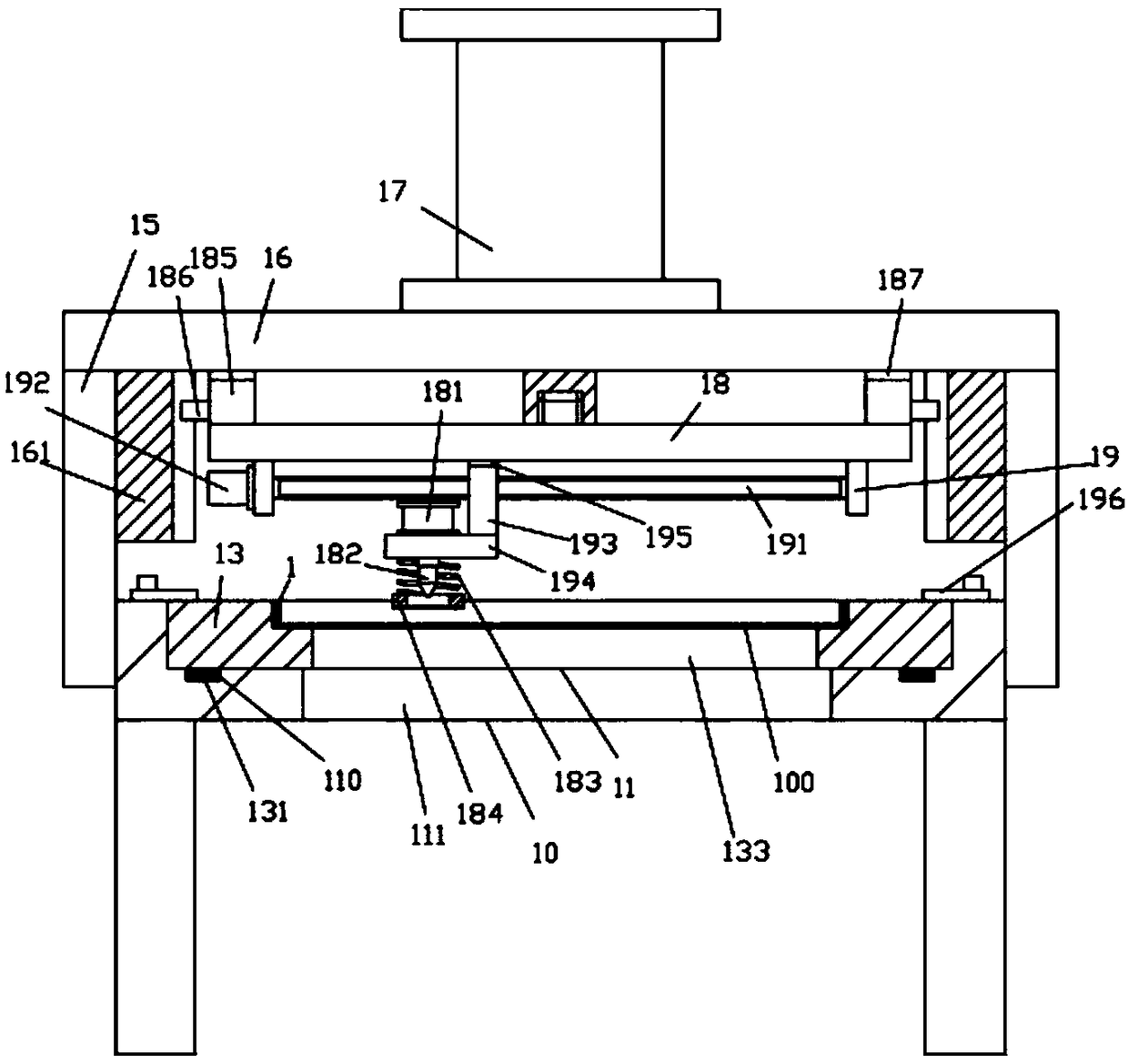
[0016] Example, see as Figure 1 to Figure 2 As shown, a control cabinet rib punching machine includes a frame 10, the top of the frame 10 has a mounting groove 11 in the middle of the top surface, and an inner mounting mold 13 is inserted into the mounting groove 11, and A plurality of permanent magnet blocks 131 are formed on the edge of the bottom surface of the mounting mold 13, and the permanent magnet blocks 131 are inserted into the positioning recesses 110 formed on the edge of the bottom surface of the mounting groove 11 and are attracted to the top plate of the frame 10;

[0017] The side wall of the top plate of the frame 10 is fixed with side support columns 15, the upper top plate 16 is fixed on the top surface of all the side support columns 15, and the middle of the top surface of the upper top plate 16 is fixed with a lifting cylinder 17, which The push rod passes through the bottom surface of the upper top plate 16 and is screwed with a lifting plate 18. The left...


PUM


Abstract

The invention discloses a control cabinet body rib strip punching machine which comprises a rack. An installation groove is formed in the middle of the top face of a top plate of the rack, an inner installation die is inserted in the installation groove in a sleeving mode, a plurality of permanent magnetic iron blocks are formed at the edge portion of the bottom face of the inner installation die,the permanent magnetic iron blocks are inserted in positioning concaved holes formed on the edge portion of the bottom face of the installation groove in a sleeving mode and adsorbed with the top plate of the rack. Side supporting columns are fixed to the side wall of the top plate of the rack, an upper top plate is fixed to the top faces of all the side supporting columns, a lifting oil cylinderis fixed to the middle of the top face of the upper top plate, a pushing rod of the lifting oil cylinder passes through the bottom face of the upper top plate and is connected with a lifting plate ina screwed mode, side supporting plates are fixed to the left and right sides of the bottom face of the lifting plate, the two ends of a transverse moving screw rod are hinged to the two side supporting plates, and a moving motor is fixed to the outer side wall of one of the side supporting plates. According to the control cabinet body rib strip punching machine, to-be-machined rib strips can be punched continuously, the to-be-machined rib strips are not required to be moved, safety is achieved, the efficiency is high, and the effect is good.

Description

Technical field: [0001] The invention relates to the technical field of electrical control manufacturing equipment, and more specifically to a rib punching machine for a control cabinet body. Background technique: [0002] At present, the existing control cabinets generally need to be welded or bolted to connect and install the ribs, and the ribs generally need to be punched to facilitate installation, and the general ribs need to be punched with multiple through holes. The existing The method is to punch one hole at a time, and it needs to move the ribs to realize the punching. Each movement is manual movement, which is very troublesome, and it is easy to be injured when moving, which has safety hazards, is very troublesome and efficient. low. Summary of the invention: [0003] The purpose of the present invention is to overcome the shortcomings of the prior art and provide a control cabinet rib punching machine, which can continuously punch the ribs to be processed without movi...

Claims


Application Information

Patent Timeline
Patent Type & Authority Applications(China)
IPC IPC(8): B21D28/24B21D37/04
CPCB21D28/24B21D37/04
Inventor 徐亚维
Owner DONGGUAN LIANZHOU INTPROP OPERATION MANAGEMENT CO LTD
Why Eureka
Try Eureka