Magnetic field control type electric arc robot additive manufacturing method
An arc robot and additive manufacturing technology, which is applied in the direction of manufacturing tools, arc welding equipment, welding equipment, etc., to achieve the effects of improving control accuracy, homogenizing elements, and improving the accuracy of additive molding
- Summary
- Abstract
- Description
- Claims
- Application Information
AI Technical Summary
Problems solved by technology
Method used
Image


Examples
Embodiment 1
[0036] Take the model ER130S-G high-strength steel welding wire with a diameter of 1.2mm and a 6mm thick 304 stainless steel substrate stacking straight wall as an example. The specific steps are:
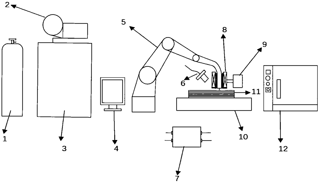
[0037] S1: Clean the surface of the 304 stainless steel substrate, remove surface impurities and oxides, open the protective gas cylinder, and prepare for the arc additive;
[0038] S2: Determine the welding process parameters. In this example, the wire feeding speed is set to 7.2mm / min, and the welding speed is set to 11mm / s;
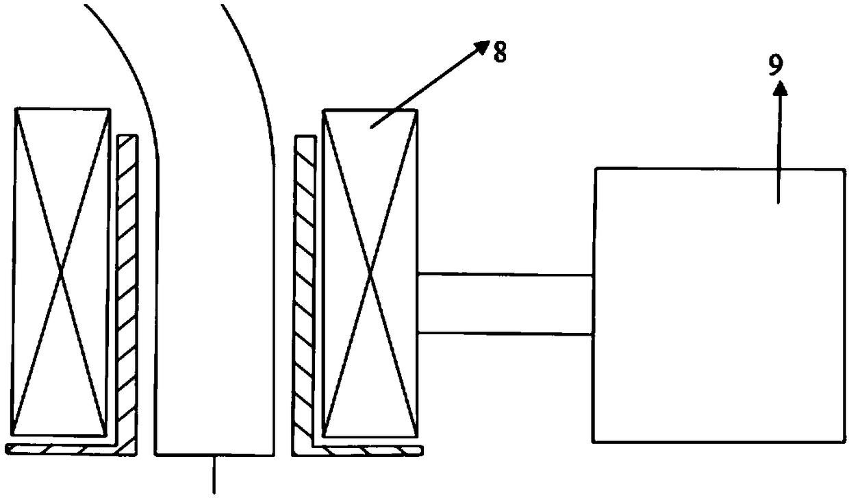
[0039] S3: Adjust the distance between the excitation coil and the workpiece. In this example, the distance between the excitation coil and the workpiece is set to 20mm;
[0040] S4: Adjust the magnitude of the excitation current. In this example, the excitation current is set to 1A;
[0041] S5: Adjust the frequency of the magnetic field. In this example, the frequency of the magnetic field is set to 10Hz;
[0042] S6: Import the three-dimensional soli...
Embodiment 2
[0048]Take the model ER130S-G high-strength steel welding wire with a diameter of 1.2mm and a 6mm-thick 304 stainless steel substrate with a straight wall as an example. The specific steps are:
[0049] S1: Clean the surface of the 304 stainless steel substrate, remove the surface debris and oxides, open the protective gas cylinder, and prepare for the arc additive;
[0050] S2: Determine the welding process parameters. In this example, the wire feeding speed is set to 7mm / min, and the welding speed is set to 10mm / s;
[0051] S3: Adjust the distance between the excitation coil and the workpiece. In this example, the distance between the excitation coil and the workpiece is set to 15mm;
[0052] S4: Adjust the size of the excitation current. In this example, the excitation current is set to 1.5A;
[0053] S5: Adjust the frequency of the magnetic field, in this example, the frequency of the magnetic field is set to 15Hz;
[0054] S6: The three-dimensional solid part model di...
Embodiment 3
[0060] Taking the model ER130S-G high-strength steel welding wire with a diameter of 1.2mm and a 6mm-thick 304 stainless steel substrate stacking block as an example, the specific steps are:
[0061] S1: Clean the surface of the 304 stainless steel substrate, remove the surface debris and oxides, open the protective gas cylinder, and prepare for the arc additive;
[0062] S2: Determine the welding process parameters. In this example, the wire feeding speed is set to 7.5mm / min, and the welding speed is set to 12mm / s;
[0063] S3: Adjust the distance between the excitation coil and the workpiece. In this example, the distance between the excitation coil and the workpiece is set to 25mm;
[0064] S4: Adjust the size of the excitation current. In this example, the excitation current is set to 2.5A;
[0065] S5: Adjust the frequency of the magnetic field, in this example, the frequency of the magnetic field is set to 20Hz;
[0066] S6: The three-dimensional solid part model diag...
PUM
| Property | Measurement | Unit |
|---|---|---|
| diameter | aaaaa | aaaaa |
| diameter | aaaaa | aaaaa |
Abstract
Description
Claims
Application Information
 - Generate Ideas
- Intellectual Property
- Life Sciences
- Materials
- Tech Scout
- Unparalleled Data Quality
- Higher Quality Content
- 60% Fewer Hallucinations
Browse by: Latest US Patents, China's latest patents, Technical Efficacy Thesaurus, Application Domain, Technology Topic, Popular Technical Reports.
© 2025 PatSnap. All rights reserved.Legal|Privacy policy|Modern Slavery Act Transparency Statement|Sitemap|About US| Contact US: help@patsnap.com