Locking device of robot

A robot and locking technology, applied in the direction of manipulators, manufacturing tools, etc., can solve the problems of increasing production expenses, errors, and time delays, and achieve the effect of increasing production expenses

Inactive Publication Date: 2019-01-04
徐州木牛流马机器人科技有限公司
View PDF7 Cites 0 Cited by
  • Summary
  • Abstract
  • Description
  • Claims
  • Application Information

AI Technical Summary

Problems solved by technology

[0002] In many industries, robots have gradually replaced manpower. However, in the process of work, due to the program or other reasons, the robot will appear stuck or have wrong steps during the work process. This requires The staff stopped the machine in time. Usually, the switch cannot be used to turn off the machine. It is necessary to manually adjust the knob to turn off the switch. Time is wasted, and the knob will be damaged, not only the machine cannot be turned off, but also the production cost will be increased

Method used


Image

  • Locking device of robot

Examples


Embodiment Construction

[0010] In order to make the object, technical solution and advantages of the present invention clearer, the present invention will be further described in detail below through the accompanying drawings and embodiments. However, it should be understood that the specific embodiments described here are only used to explain the present invention, and are not intended to limit the scope of the present invention.

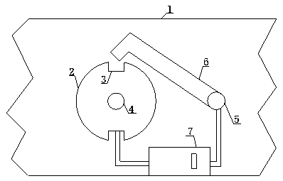
[0011] Such as figure 1 As shown, a locking device for a robot used in the present invention includes a housing 1, a gear plate 2, a groove 3, buckle I4, buckle II5, a chuck head 6 and a control system 7, and the gear plate 2 passes through the lock The buckle Ⅰ4 is fixed on the shell 1, and the surface of the gear plate 2 is provided with two grooves 3, the chuck 6 is fixedly installed on the shell 1 through the buckle Ⅱ5, and the control system 7 is connected to the buckle Ⅰ4 through wires, and the other way Connect buckle II 5, described control system 7 is made up of...


PUM


Abstract

The invention discloses a locking device of a robot. The locking device comprises a shell, a gear disc, grooves, a buckle I, a buckle II, a clamp head and a control system. The gear disc is fixed to the shell through the buckle I. The two grooves are formed on the surface of the gear disc. The clamp head is fixedly mounted on the shell through the buckle II. Through an electric wire, one way of the control system is connected with the buckle I, and the other way of the control system is connected with the buckle II. The control system is composed of a switch, a single-chip microcomputer, a power source and a divider, the switch is connected with the single-chip microcomputer, the single-chip microcomputer is connected with the power source, and the power source is connected with the divider. The situation that a rotary knob cannot be twisted in place at a time during manual adjustment cannot happen, the work time cannot be wasted, the rotary knob cannot be damaged, a machine can be shut down fast, and production expenditures cannot be increased.

Description

technical field [0001] The invention relates to a locking device, in particular to a locking device for a robot. Background technique [0002] In many industries, robots have gradually replaced manpower. However, in the process of work, due to the program or other reasons, the robot will appear stuck or have wrong steps during the work process. This requires The staff stopped the machine in time. Usually, the switch cannot be used to turn off the machine. It is necessary to manually adjust the knob to turn off the switch. Time is wasted, and the knob will be damaged, not only the machine cannot be turned off, but also the production cost will be increased. Contents of the invention [0003] Aiming at the problems existing in the above-mentioned prior art, the present invention provides a locking device for a robot, which prevents the situation that the knob cannot be screwed in place at one time during manual adjustment, does not delay working time, does not damage the kn...

Claims


Application Information

Patent Timeline
Patent Type & Authority Applications(China)
IPC IPC(8): B25J13/00
CPCB25J13/00
Inventor 杨越华
Owner 徐州木牛流马机器人科技有限公司
Why Eureka
Try Eureka