
Wood board cutting device

A cutting device and wood board technology, which is applied in wood processing equipment, special shaping/shaping machines, manufacturing tools, etc., can solve the problems of hard work, increased frequency of saw blade replacement, and uneven edge cutting of wood boards, etc., and achieve the cost of use It will not cause fire, the qualified rate of wood cutting is high, and the workers can work easily.

Inactive Publication Date: 2019-01-04
湖州南浔登越家居有限公司
View PDF0 Cites 1 Cited by
  • Summary
  • Abstract
  • Description
  • Claims
  • Application Information

AI Technical Summary

Problems solved by technology

In the process of pushing the wood board, due to the vibration of the saw blade cutting, it is difficult to ensure that the wood board and the backing board are always in close contact, resulting in the cutting edge of the wood board may not be straight, reducing the pass rate of wood board cutting
Since the wooden board is in close contact with the backing board during the pushing process, the frictional force when the wooden board is pushed is relatively large, and the force required to push the wooden board is relatively large, and the workers work hard
In addition, the saw blade tends to generate heat during long-term continuous cutting of wood, especially when cutting thicker and harder wood, which causes overheating of the saw blade, thereby reducing the service life of the saw blade and increasing the The replacement frequency of blades increases the cost of using the table saw, and it may also ignite wood chips and cause a fire
Therefore, the existing sliding table saw has the disadvantages of low qualified rate of plank cutting, relatively hard work of workers, high use cost and possible fire hazard.

Method used


Image

  • Wood board cutting device
  • Wood board cutting device
  • Wood board cutting device

Examples


Embodiment Construction

[0013] The present invention will be further described below in conjunction with the drawings and embodiments, but it is not a basis for limiting the present invention.

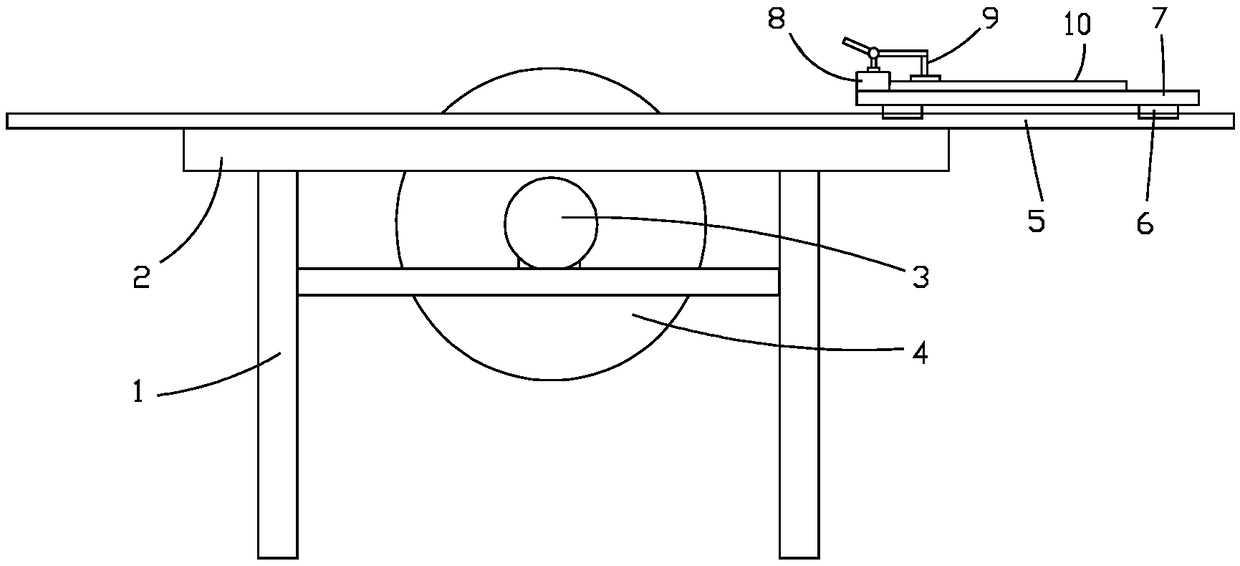
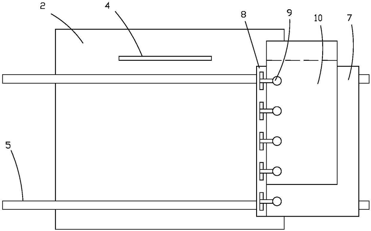
[0014] Examples. Wood cutting device, such as figure 1 As shown, the frame 1 is included. The top of the frame 1 is provided with a platen 2, and the frame 1 is provided with a motor 3 fixed to the frame 1, and the output end of the motor 3 is provided with a saw blade 4 and a saw blade 4 The top passes through the table 2 vertically. Two rails 5 fixed to the table 2 are provided on the same side of the saw blade 4. The rails 5 are connected to the slide plate 7 through the sliding block 6. The slide plate 7 is provided with a backing plate 8 perpendicular to the saw blade 4 , The backing plate 8 is provided with a row of quick clamps 9; the saw blade 4 includes a copper core plate 41, the outer peripheral surface of the copper core plate 41 is provided with a plurality of ventilation holes 42, and both sides of...


PUM


Abstract

The invention discloses a wood board cutting device which comprises a stand, wherein a platen is arranged at the top of the stand; a motor is arranged in the stand; a saw web is arranged at the outputend of the motor; the top of the saw web perpendicularly passes through the platen; two rails fixed on the platen are arranged on the same side of the saw web; the rails are connected with a slidingplate through a sliding block; a backup plate perpendicular to the saw web is arranged on the sliding plate; a row of quick clamps are arranged on the backup plate; the saw web comprises a copper coredisk; multiple ventilating holes are formed in the peripheral surface of the copper core disk; cutting disks are arranged on two sides of the copper core disk; fixing holes passing through the coppercore disk are formed in the cutting disks; the outer edges of the cutting disks outwards extend out of the outer edge of the copper core disk; multiple sawteeth are arranged on the peripheral surfaces of the cutting disks; 10 to 15 sawteeth form one group; one sawtooth in each group of sawteeth is inclined outwards; one sawtooth in each group of sawteeth is inclined inwards. The wood board cutting device disclosed by the invention has the advantages of relatively high wood board cutting qualification rate, relatively low workload of a worker, relatively low use cost and no fire.

Description

Technical field [0001] The field belongs to the field of sliding table saws for wood board cutting, and particularly relates to a wood board cutting device. Background technique [0002] The sliding table saw is one of the commonly used equipment for wood cutting. Place the wood on the work surface of the sliding table saw. The worker puts one side of the wood against the backing board of the sliding table saw, and then pushes the board so that all the wood passes through the sliding table saw. The saw blade can complete the cutting of the board. In the process of pushing the wood board, it is difficult to ensure the close contact between the wood board and the backing board due to the vibration of the saw blade cutting, resulting in the cutting edge of the wood board may not be straight, which reduces the pass rate of wood board cutting. Since the wooden board is in close contact with the supporting board during the pushing process, the friction force when the wooden board is p...

Claims


Application Information

Patent Timeline
IPC IPC(8): B27C5/02
CPCB27C5/02
Inventor 张王静
Owner 湖州南浔登越家居有限公司
Learn More