Line color spraying equipment used for textile process

A line and color-spraying technology, which is applied in the processing of textile material equipment configuration, textile and papermaking, and textile material processing, can solve problems such as dye line bonding

Inactive Publication Date: 2019-01-04
傅云峰
View PDF4 Cites 4 Cited by
  • Summary
  • Abstract
  • Description
  • Claims
  • Application Information

AI Technical Summary

Problems solved by technology

[0004] In order to overcome the current dyeing method when dyeing the lines, the dyes in the lines will be too full, and the lines will not be dried to cause bonding. The technical problem to be solved is: to provide a method for spraying the lines The color will not make the dye in the thread too full, and the thread can be dried without causing sticking. Textile line color spraying equipment

Method used


Image

  • Line color spraying equipment used for textile process
  • Line color spraying equipment used for textile process
  • Line color spraying equipment used for textile process

Examples


Embodiment 1

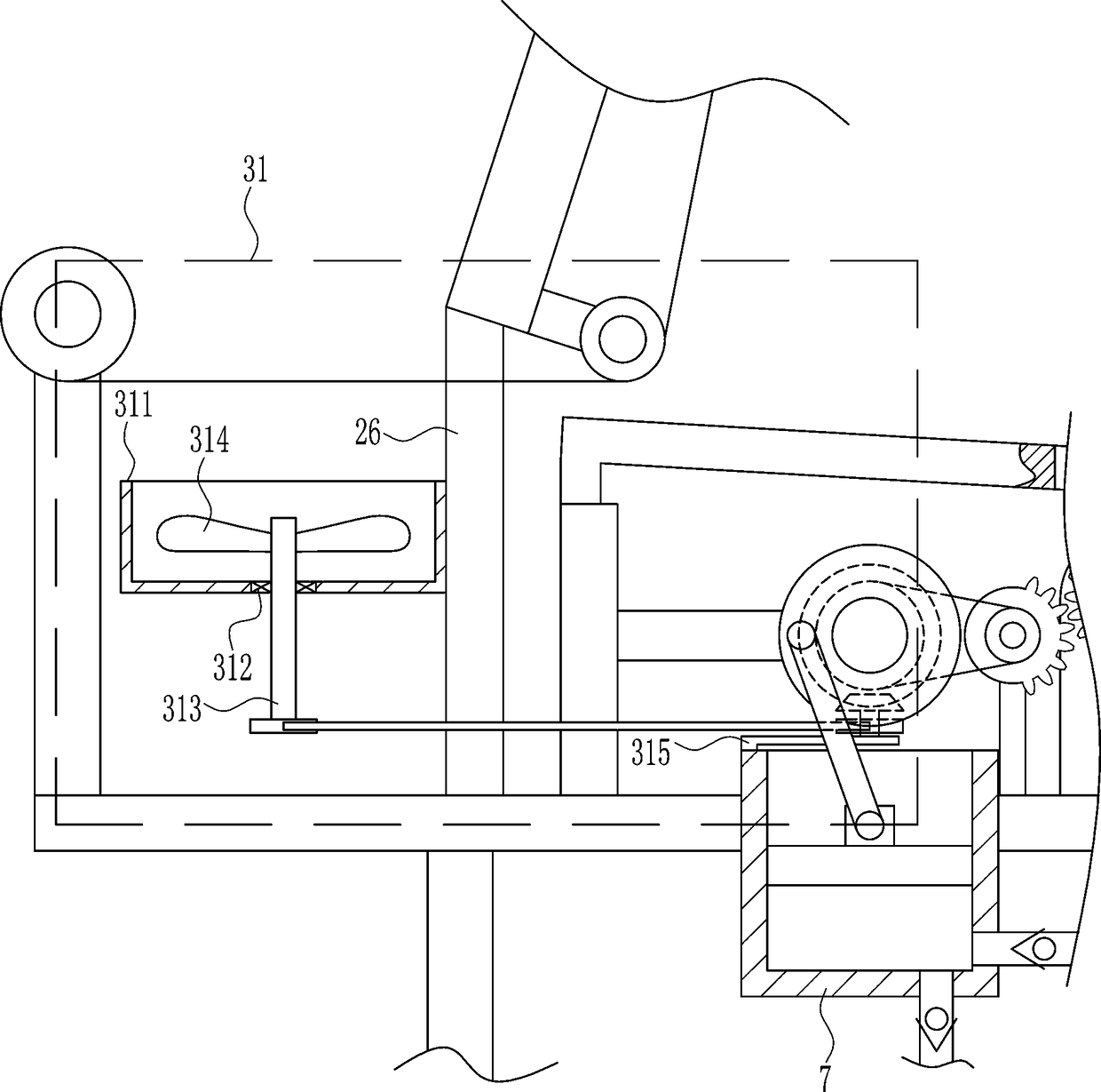
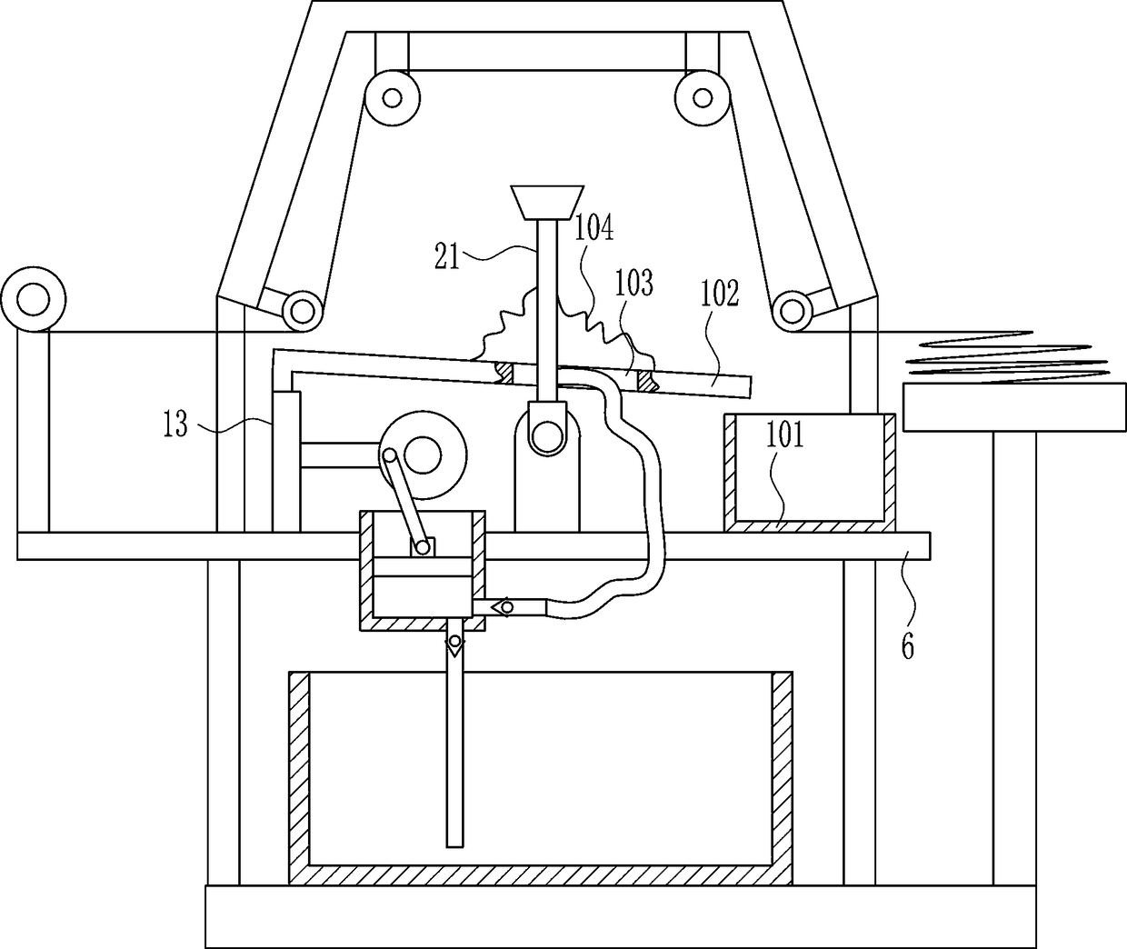
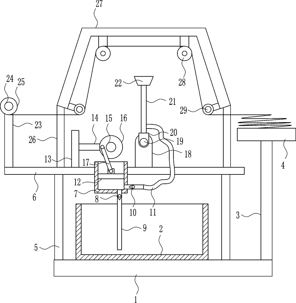
[0025] A kind of line color spraying equipment for weaving, such as Figure 1-6 As shown, it includes a base plate 1, a dye box 2, a first support rod 3, a placement plate 4, a second support rod 5, a mounting plate 6, a piston cylinder 7, a first one-way valve 8, a feed pipe 9, a second Check valve 10, hose 11, piston block 12, connecting rod 13, connecting block 14, first electric wheel 15, turntable 16, rocker 17, mounting block 18, rotating shaft 19, rotating block 20, nozzle pipe 21, nozzle 22. Fixed rod 23, second electric wheel 24, reel 25, support 26, U-shaped plate 27, first roller 28 and second roller 29, dye box 2 is placed on the bottom plate 1, and the right side of the bottom plate 1 is connected There is a first support rod 3, the upper end of the first support rod 3 is connected with a placement plate 4, the left side of the bottom plate 1 is connected with a second support rod 5, the upper end of the second support rod 5 is connected with a mounting plate 6, a...

Embodiment 2

[0027] A kind of line color spraying equipment for weaving, such as Figure 1-6 As shown, it includes a base plate 1, a dye box 2, a first support rod 3, a placement plate 4, a second support rod 5, a mounting plate 6, a piston cylinder 7, a first one-way valve 8, a feed pipe 9, a second Check valve 10, hose 11, piston block 12, connecting rod 13, connecting block 14, first electric wheel 15, turntable 16, rocker 17, mounting block 18, rotating shaft 19, rotating block 20, nozzle pipe 21, nozzle 22. Fixed rod 23, second electric wheel 24, reel 25, support 26, U-shaped plate 27, first roller 28 and second roller 29, dye box 2 is placed on the bottom plate 1, and the right side of the bottom plate 1 is connected There is a first support rod 3, the upper end of the first support rod 3 is connected with a placement plate 4, the left side of the bottom plate 1 is connected with a second support rod 5, the upper end of the second support rod 5 is connected with a mounting plate 6, a...

Embodiment 3

[0030] A kind of line color spraying equipment for weaving, such as Figure 1-6 As shown, it includes a base plate 1, a dye box 2, a first support rod 3, a placement plate 4, a second support rod 5, a mounting plate 6, a piston cylinder 7, a first one-way valve 8, a feed pipe 9, a second Check valve 10, hose 11, piston block 12, connecting rod 13, connecting block 14, first electric wheel 15, turntable 16, rocker 17, mounting block 18, rotating shaft 19, rotating block 20, nozzle pipe 21, nozzle 22. Fixed rod 23, second electric wheel 24, reel 25, support 26, U-shaped plate 27, first roller 28 and second roller 29, dye box 2 is placed on the bottom plate 1, and the right side of the bottom plate 1 is connected There is a first support rod 3, the upper end of the first support rod 3 is connected with a placement plate 4, the left side of the bottom plate 1 is connected with a second support rod 5, the upper end of the second support rod 5 is connected with a mounting plate 6, a...


PUM


Abstract

The invention relates to textile equipment and especially relates to line color spraying equipment used for a textile process. By using the line color spraying equipment used for the textile process provided in the invention, color spraying is performed on a line and dye in the line is not too full, and the line is dried without bonding. The line color spraying equipment used for the textile process comprises a base plate, a dye box, a first support rod, a placing plate, a second support rod, an installation plate and the like. The dye box is placed on the base plate. The right side of the base plate is connected to the first support rod. The upper end of the first support rod is connected to the placing plate. The left side of the base plate is connected to the second support rod. In theinvention, color spraying is performed on a line and the dye in the line is not too full, and the line is dried without bonding; and the moving line is adopted so that a spray nozzle waveringly sprayscolor on the line, the color can be sprayed to the line surface and the dye in the line is not too full, and the color can be uniformly sprayed to the line.

Description

technical field [0001] The invention relates to textile equipment, in particular to a line color spraying equipment for textile. Background technique [0002] The original meaning of textile is taken from the general term of spinning and weaving, but with the continuous development and improvement of the textile knowledge system and subject system, especially after the emergence of non-woven textile materials and three-dimensional composite weaving technologies, textile is not only the traditional spinning and weaving Weaving also includes non-woven technology, three-dimensional weaving technology, electrostatic nano-netting technology, etc. [0003] At present, when dyeing the lines, most of the lines are placed directly in the dye vat and then moved, but the current dyeing method will make the dye in the lines too full, resulting in overflow after the lines are collected, and It will also cause a waste of resources. If the lines are not dried, it will cause sticking after...

Claims


Application Information

Patent Timeline
Patent Type & Authority Applications(China)
IPC IPC(8): D06B1/02D06B23/20D06B15/00
CPCD06B1/02D06B15/00D06B23/20
Inventor 傅云峰
Owner 傅云峰
Why Eureka
Try Eureka