
Snap-on composite guardrail

A composite, snap-on technology, used in railings, roads, instruments, etc., can solve the problems of affecting the connection, the position of the connection is easy to deviate, and the processing is cumbersome, so as to reduce the number of punching holes and meet the needs of large quantities. , the effect of increasing economic benefits

Inactive Publication Date: 2019-01-04
JIANGSU YANGGUANG NOVAL FENCE SCI & TECH CO LTD
View PDF1 Cites 0 Cited by
  • Summary
  • Abstract
  • Description
  • Claims
  • Application Information

AI Technical Summary

Problems solved by technology

[0002] Generally, there are two ways to connect the vertical bars of the guardrail and the upper and lower horizontal bars. One is to weld the guardrail as a whole, and the other is to insert plug-in components. The welding method cannot be recycled, and the welding In the process, it is easy to deviate from the appearance of the product and other phenomena. Among them, the plug-in plug-in component needs to open two small through holes at both ends of each vertical rod, so the processing is cumbersome. If the rubber sealing ring is damaged, its connection will be affected. For example, the patent application publication number CN 202108017 U discloses a clip-on composite guardrail, the length of the clip body is less than the length of the special-shaped hole and larger than the length of the special-shaped hole The upper surface of the lower cross bar is provided with a square hole, and the protrusion includes a convex body and a welding body positioned above the convex body; the length of the convex body is less than the length of the square hole, and the width of the convex body Smaller than the width of the square hole, but the above patents require internal welding during use, the process is complex and costly, and cannot meet the cost requirements, and the position of the connection is prone to deviation

Method used


Image

  • Snap-on composite guardrail
  • Snap-on composite guardrail
  • Snap-on composite guardrail

Examples


Embodiment Construction

[0016] The following will clearly and completely describe the technical solutions in the embodiments of the present invention with reference to the accompanying drawings in the embodiments of the present invention. Obviously, the described embodiments are only some, not all, embodiments of the present invention. Based on the embodiments of the present invention, all other embodiments obtained by persons of ordinary skill in the art without making creative efforts belong to the protection scope of the present invention.

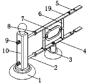
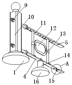
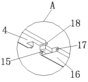
[0017] see Figure 1-4 , the present invention provides a technical solution: a snap-fit ​​composite guardrail, including a base 1, a column 10 is provided on the upper side of the base 1, and two sets of through holes symmetrically distributed are provided on both sides of the middle position of the column 10, through which A connecting rod 2 is provided in the middle of the hole for the connection between the first horizontal guardrail 4 and the column 10. O...


PUM


Abstract

The invention discloses a snap-on composite guardrail, including a base, the upper side of the base is provided with upright columns, two sets of symmetrically distributed through holes are arranged on both sides of the middle position of the upright column, a connecting rod is arranged at the inner middle position of the through hole, one end of the connecting rod is connected with the upright post through a hexagon bolt, the other end of the connecting rod is connected with one side of the retaining ring, one side of the other set of first transverse guard rails is provided with two or moresets of arc-shaped skateboards which are equally spaced apart, one end of the vertical guardrail is connected to one side of the arc-shaped slide plate close to the clamping hole, the other end of thevertical guardrail is connected with the first transverse guardrail through a clamping hole, through the design of the clamping hole, the positioning hole and the positioning column, the whole guardrail does not need to be welded, the process is simple and the cost is low, the cost can be reduced, the number of holes punched on the railing body is reduced through the design of the arc-shaped slide plate, the public notice board and the pasting groove can be popularized in commercial advertisement, and the economic benefit can be increased.

Description

technical field [0001] The invention relates to the technical field of guardrails, in particular to a clamping composite guardrail. Background technique [0002] Generally, there are two ways to connect the vertical bars of the guardrail and the upper and lower horizontal bars. One is to weld the guardrail as a whole, and the other is to insert plug-in components. The welding method cannot be recycled, and the welding In the process, it is easy to deviate from the appearance of the product and other phenomena. Among them, the plug-in plug-in component needs to open two small through holes at both ends of each vertical rod, so the processing is cumbersome. If the rubber sealing ring is damaged, its connection will be affected. For example, the patent application publication number CN 202108017 U discloses a clip-on composite guardrail, the length of the clip body is less than the length of the special-shaped hole and larger than the length of the special-shaped hole The uppe...

Claims


Application Information

Patent Timeline
IPC IPC(8): E01F15/02E04F11/18G09F23/00
CPCE01F15/02E04F11/181E04F11/1836E04F2011/1868G09F23/00G09F2023/0016
Inventor 严宇航孙青艳管金月严峰杰
Owner JIANGSU YANGGUANG NOVAL FENCE SCI & TECH CO LTD
Learn More