Vehicle with power swinging door and position-based torque compensation method

A swing door, electric technology, applied to vehicle components, emergency protection circuit devices, doors, etc., can solve the problem of increasing quality

Active Publication Date: 2019-01-04
GM GLOBAL TECH OPERATIONS LLC
View PDF5 Cites 11 Cited by
  • Summary
  • Abstract
  • Description
  • Claims
  • Application Information

AI Technical Summary

Problems solved by technology

Each component accommodated adds additional mass to the door

Method used


Image

  • Vehicle with power swinging door and position-based torque compensation method
  • Vehicle with power swinging door and position-based torque compensation method
  • Vehicle with power swinging door and position-based torque compensation method

Examples


Embodiment Construction

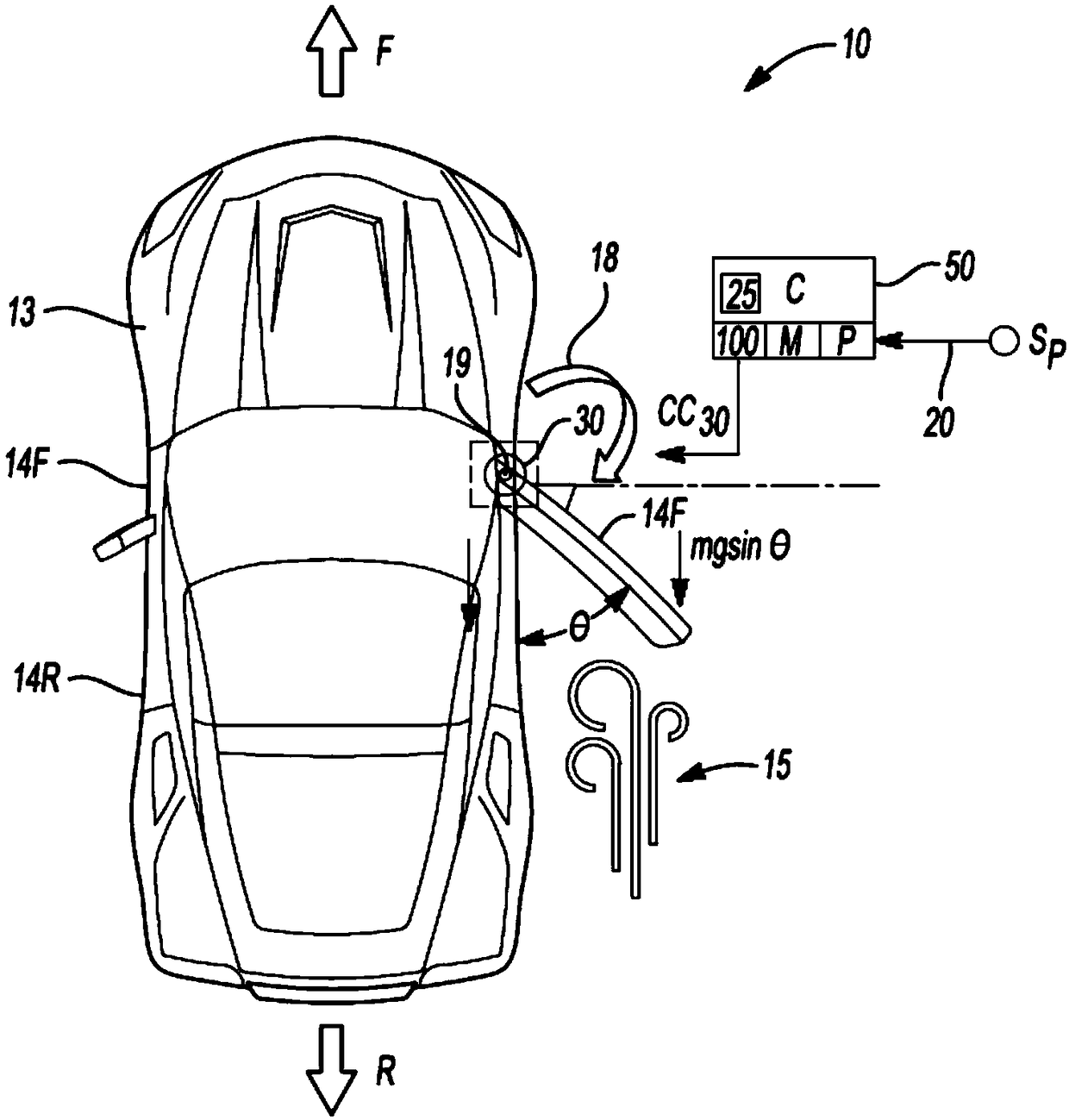
[0014] Referring to the drawings, wherein like reference numerals refer to like components throughout the figures, an exemplary motor vehicle 10 has corresponding forward (arrow F) and rearward (arrow R) driving directions. The vehicle 10 includes a body 13 , a power swinging front side door 14F that opens and closes relative to the body 13 , and optionally a pair of substantially similar power swinging rear side doors 14R. Front and rear side doors 14F and 14R are configured to swing or rotate about door pivot 19 as indicated by arrow 18 to a desired angular position (θ), such as 0 to 90 degrees from the longitudinal axis of vehicle 10 .

[0015] The side doors 14F and 14R undergo an opening / closing motion in response to an applied door force. As configured herein, such applied door forces are applied in whole or in part to doors 14F and 14R by rotary actuators 30, such as electric door motors, operatively connected to doors 14F and 14R near corresponding pivots 19. superior...


PUM


Abstract

A system controls opening / closing of a power swinging door, e.g., in a vehicle, and includes a rotary actuator, position sensor, and controller. In a controller-executed method, the actuator applies torque to the door in response to control signals. The controller uses a measured raw angular position from the sensor to determine wind- or grade-based external forces acting on the door during opening or closing, and adjusts the actuator torque in response to the external forces. The sensor may be a rotary encoder, with the actuator being an electric motor. Lookup tables contain data relating oscillation to the external forces. The controller may induce door oscillation and to relate oscillation decay to the external forces. An obstacle-based current threshold may be adjusted in response to the external forces.

Description

Background technique [0001] Motor vehicles include swinging side doors that allow occupants to enter and exit the vehicle interior. With such doors, an occupant pulls on the outer door handle, which actuates a lever mechanism located inside the door. Once unlocked, the door pivots about the pivot in any position including fully closed and fully open positions. The swing side doors house the power window and folding mirror controls, door locking mechanism, support structure and latching mechanism. Each component accommodated adds additional mass to the door. Therefore, to assist in the opening and closing of the swing side door, the door may be equipped with a rotary actuator, such as an electric door motor that powers the opening and closing functions. Contents of the invention [0002] Disclosed herein is a system for controlling the opening and closing functions of electrically powered swinging doors of the type described above, such as swinging side doors, rear doors, ...

Claims


Application Information

Patent Timeline
Patent Type & Authority Applications(China)
IPC IPC(8): E05F15/611E05F15/40E05F15/70B60J5/04
CPCE05F15/40E05F15/611E05F15/70B60J5/047E05Y2900/531H02H7/0851E05Y2400/326E05Y2400/36E05Y2400/44E05Y2900/50H02H3/006E05F15/71E05F15/75
Inventor B·阮伯莱酷C·J·夏米
Owner GM GLOBAL TECH OPERATIONS LLC
Why Eureka
Try Eureka