Steel wire rope transmission mechanism for photoelectric pod

A technology of transmission mechanism and photoelectric pod, applied in transmission devices, aircraft parts, mechanical equipment, etc., can solve the problems of excessive volume, low transmission precision, insufficient power, etc., and achieve the effect of small volume and high transmission precision

Active Publication Date: 2019-01-04
TIANJIN JINHANG INST OF TECH PHYSICS
6 Cites 0 Cited by

AI-Extracted Technical Summary

Problems solved by technology

[0004] The technical problem to be solved by the present invention is: how to solve the problems of low transmission precision...

Abstract

The invention relates to a steel wire rope transmission mechanism for a photoelectric pod, and belongs to the technical field of transmission mechanisms. The mechanism is characterized in that a reasonable transmission mode is carried out, and the mechanism is high in transmission accuracy and small in size and is capable of loading 0.5kg; and the problems of low transmission accuracy, excessivelylarge size and insufficient power of a traditional transmission mechanism for a pitch axis of a photoelectric pod can be solved.

Application Domain

Aircraft componentsGearing

Technology Topic

EngineeringWire rope +1

Image

  • Steel wire rope transmission mechanism for photoelectric pod
  • Steel wire rope transmission mechanism for photoelectric pod
  • Steel wire rope transmission mechanism for photoelectric pod

Examples

  • Experimental program(1)

Example Embodiment

[0020] In order to make the purpose, content, and advantages of the present invention clearer, the specific implementation manners of the present invention will be further described in detail below in conjunction with the accompanying drawings and embodiments.
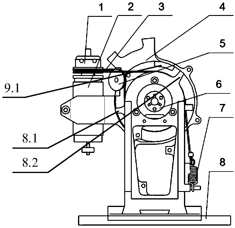
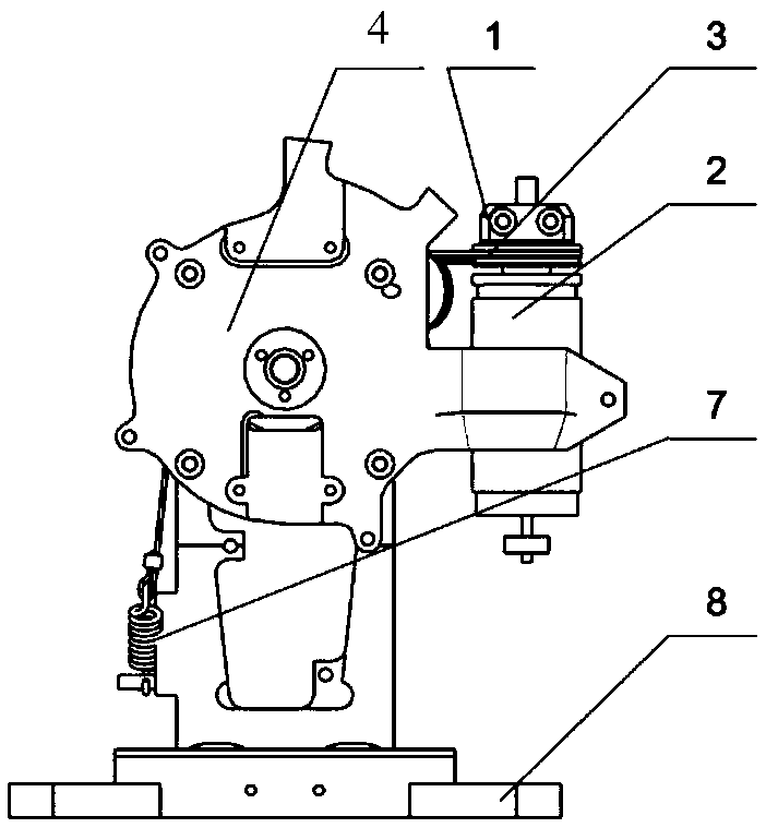
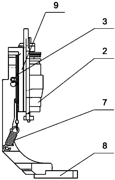
[0021] like Figure 1 to Figure 4 As shown, the present invention relates to a wire rope transmission mechanism of a photoelectric pod, including a wire rope small wheel 1, a driving motor 2, a wire rope 3, an outer pitch frame 4, an outer pitch wire rope pulley 5, a clamping ring 6, a preload spring 7, Outer pitching main support 8, outer pitching limit ring 9, wire rope bull wheel 10 and screw 11.
[0022] Wherein, the outer pitch limiting ring 9 is provided with a boss 9.1, which can perform pitching motion together with the outer pitching mechanism, and the upper boss 8.1, lower The boss 8.2 is used to block the outer pitch limit ring 9 at the position of the boss 9.1 of the outer pitch limit ring 9 so as to limit the range of motion of the outer pitch limit ring 9. In this embodiment, the upper boss of the outer pitch main support 8 The position of 8.1 is -20°, and the position of lower boss 8.2 is +110°. The outer pitching main support 8 is a support mechanism, which is fixed in the system, and its upper boss 8.1, lower boss 8.2 cooperates with the boss 9.1 of the outer pitch limit ring 9 to make the outer pitch mechanism move from -20° to +110°, steel wire rope pulley 10, preload spring 7 are fixed on the outer pitching main support 8; wire rope small wheel 1, drive motor 2, steel wire rope 3, outer pitching frame 4, outer pitching wire rope pulley 5, clamping ring 6, The outer pitch limit ring 9 forms the outer pitch mechanism, and the outer pitch mechanism is installed on the outer pitch main support 8 to perform pitch movement; the outer pitch frame 4 and the outer pitch limit ring 9 are clamped with a bearing outer ring by screws, and the bearing inner ring It is fixed on the steel wire rope pulley 10; the clamping ring 6 is fixed on the central axis of the outer pitching frame 4, and there are three claws inside which can clamp the load through screw locking, so that the load can do pitching motion together with the outer pitching frame 4; the steel wire rope 3. The middle is fixed on the small wire rope pulley 1, and the two ends pass through the side of the small wire rope pulley 1, and one end goes around the outer pitching wire rope pulley 5, and the large wire rope pulley 10 is fixed on the outer pitching main support 8 using the screws 11, and the other end Bypass the wire rope pulley 10 and connect to the pretension spring 7 and fix it on the outer pitch main support 8; the wire rope pulley 10 and the outer pitch wire rope pulley 5 act as fixed pulleys to change the transmission direction of the drive motor 2, and the wire rope pulley 1 is fixed as a movable pulley On the driving motor 2; the driving motor 2 is the driving mechanism, which is clamped on the side of the outer pitching frame 4, and is driven by the outer pitching mechanism to make the load move around the wire rope pulley 10 on the outer pitching main support 8, and the outer pitching mechanism is driving Driven by the motor 2, the pitching action can be realized, and the range of motion is -20° to +110°, where 0° is the horizontal direction, which is figure 1 position, clockwise to -20° position is the limit position, counterclockwise to +110° position is the limit position.
[0023] The transmission process of the above wire rope transmission mechanism is: when the drive motor 2 generates counterclockwise torque, the small wire rope wheel 1 also rotates counterclockwise, pulling the wire rope 3, and the wire rope 3 bypasses the side of the wire rope pulley 10 to tighten until the pretension spring 7 generates The reaction force makes the outer pitching mechanism move clockwise to the limit position -20°, and the boss of the outer pitching limit ring 9 of the outer pitching mechanism collides with the boss at -20° of the outer pitching main support 8, so that the outer pitching mechanism Reach the limit position; when the driving motor 2 generates a clockwise torque, the small wire rope pulley 1 also rotates clockwise, and the wire rope 3 is tightened around the side of the outer pitching wire rope pulley 5, and then goes around the large wire rope pulley 10 to the screw 11 to generate a reaction force Make the outer pitching mechanism move counterclockwise to the limit position +110°, the boss of the outer pitching limit ring 9 of the outer pitching mechanism collides with the +110° boss of the outer pitching main support 8 so that the outer pitching mechanism reaches the limit position.
[0024] Through the above structural design, the pre-tightening spring 7 can keep the steel wire rope 3 in the best mechanical state, and ensure that the transmission error is less than 60 microradians. Compared with the gear transmission, the transmission of the steel wire rope 3 has smaller backlash, smooth transmission, high transmission efficiency, and no need for lubrication. The outer pitch frame 4 can carry a load of 0.5kg through the clamping ring locking device. The volume of the outer pitch mechanism can be less than φ90mm×14mm.
[0025] The above is only a preferred embodiment of the present invention, it should be pointed out that for those of ordinary skill in the art, without departing from the technical principle of the present invention, some improvements and modifications can also be made. It should also be regarded as the protection scope of the present invention.

PUM

no PUM

Description & Claims & Application Information

We can also present the details of the Description, Claims and Application information to help users get a comprehensive understanding of the technical details of the patent, such as background art, summary of invention, brief description of drawings, description of embodiments, and other original content. On the other hand, users can also determine the specific scope of protection of the technology through the list of claims; as well as understand the changes in the life cycle of the technology with the presentation of the patent timeline. Login to view more.

Similar technology patents

Small calendaring device for producing special sealing adhesive tape for full-automatic dyed film sealing machine

InactiveCN107984667AHigh transmission precisionLarge transmission torque
Owner:HARBIN INST OF TECH +2

Hand cranking type linear guide rail taper head

InactiveCN107335876AHigh transmission precisionIt is convenient to adjust the taper and correct the verticality of the molybdenum wire
Owner:泰州市雄峰机械有限公司

Two-stroke engine

PendingCN107503819Acompact structureHigh transmission precision
Owner:WENLING JENNFENG IND

Special perforated speed reducer for straight thread rolling machine

PendingCN111963655AHigh transmission precisionreduce manufacturing cost
Owner:德州延辉机械设备有限公司

Carrying type industrial robot

ActiveCN114536394AHigh transmission precisionreduce load
Owner:SHANGHAI URBAN CONSTR VOCATIONAL COLLEGE

Classification and recommendation of technical efficacy words

  • High transmission precision
  • reduce volume

Annular rope weaving machine

ActiveCN106521801AHigh transmission precisionReset positioning without error
Owner:XUZHOU HENGHUI BRAIDING MACHINE

Direct driving type dual spindle accurate rotating platform

InactiveCN101486147AHigh transmission precisionhigh load rigidity
Owner:三六零安全科技股份有限公司 +2

Zero gap speed changing mechanism

InactiveCN1719069AHigh transmission precision
Owner:HEBEI UNIV OF TECH

High-speed linear drive mechanism for hectograph

ActiveCN101579962AHigh transmission precisionprecise positioning
Owner:广州互通气动机器工程有限公司

Posture adjusting and positioning device for assembling external culvert casing

ActiveCN110773972AHigh transmission precisionImprove carrying capacity
Owner:AVIC BEIJING AERONAUTICAL MFG TECH RES INST

Implant release mechanism

ActiveUS20080140178A1reduce volumereduce outer diameter
Owner:COOK MEDICAL TECH LLC

Speed reduction box for turbine fracturing

Owner:YANTAI JEREH PETROLEUM EQUIP & TECH

Miniature and Multi-Band RF Coil Design

ActiveUS20100090824A1reduce volumelong wavelength
Owner:HONG KONG APPLIED SCI & TECH RES INST

Automatic washing and dewatering combined device of rotary type mop

InactiveCN102370447Areduce volumeSimple structure
Owner:上海祥美网络科技有限公司 +1

Optical imaging system

ActiveUS20070008625A1reduce volumedeteriorate with time
Owner:SAMSUNG ELECTRONICS CO LTD
Why Eureka
Try Eureka