Automatic temperature control system and method

An automatic control system and controller technology, applied in heating and ventilation control system, heating and ventilation safety system, control input related to air characteristics, etc., can solve the problem of low efficiency

Inactive Publication Date: 2019-01-04
贵州鸿巨燃气热力工程有限公司
View PDF4 Cites 2 Cited by
  • Summary
  • Abstract
  • Description
  • Claims
  • Application Information

AI Technical Summary

Problems solved by technology

[0004] The purpose of the embodiments of the present invention is to provide an automatic temperature control system and method to solve the problem of low efficiency of the method for determining the working mode of the HVAC system in the prior art

Method used


Image

  • Automatic temperature control system and method
  • Automatic temperature control system and method
  • Automatic temperature control system and method

Examples


Embodiment 1

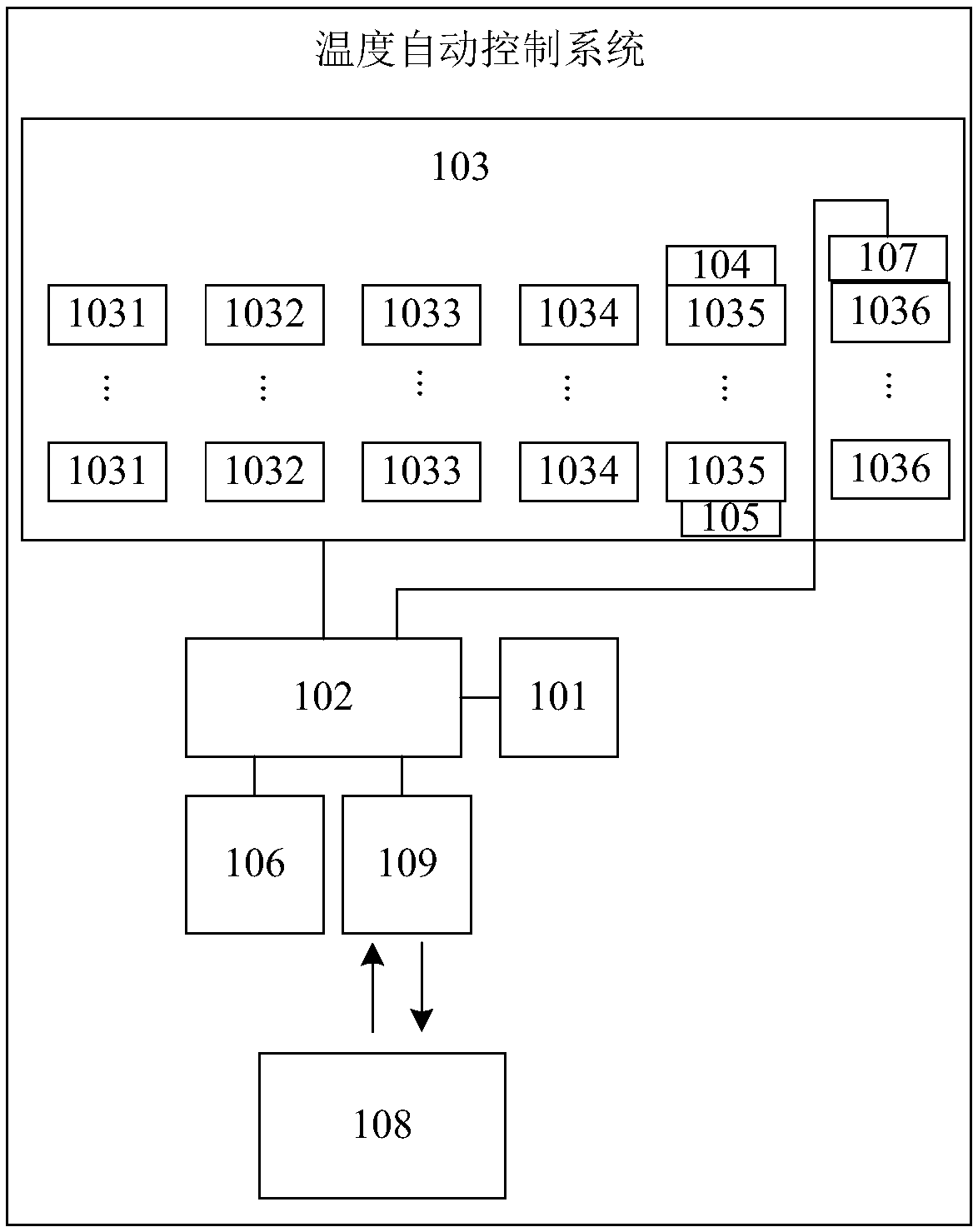
[0094] Embodiment 1 of the present invention provides an automatic temperature control system, the structural diagram of which can be found in figure 1 , figure 1 In this system, the system includes an outdoor temperature sensor 101, a controller 102, and an HVAC system 103, wherein:

[0095] The outdoor temperature sensor 101 is set outdoors;

[0096] The controller 102 is connected to the outdoor temperature sensor 101 and the HVAC system 103 respectively;

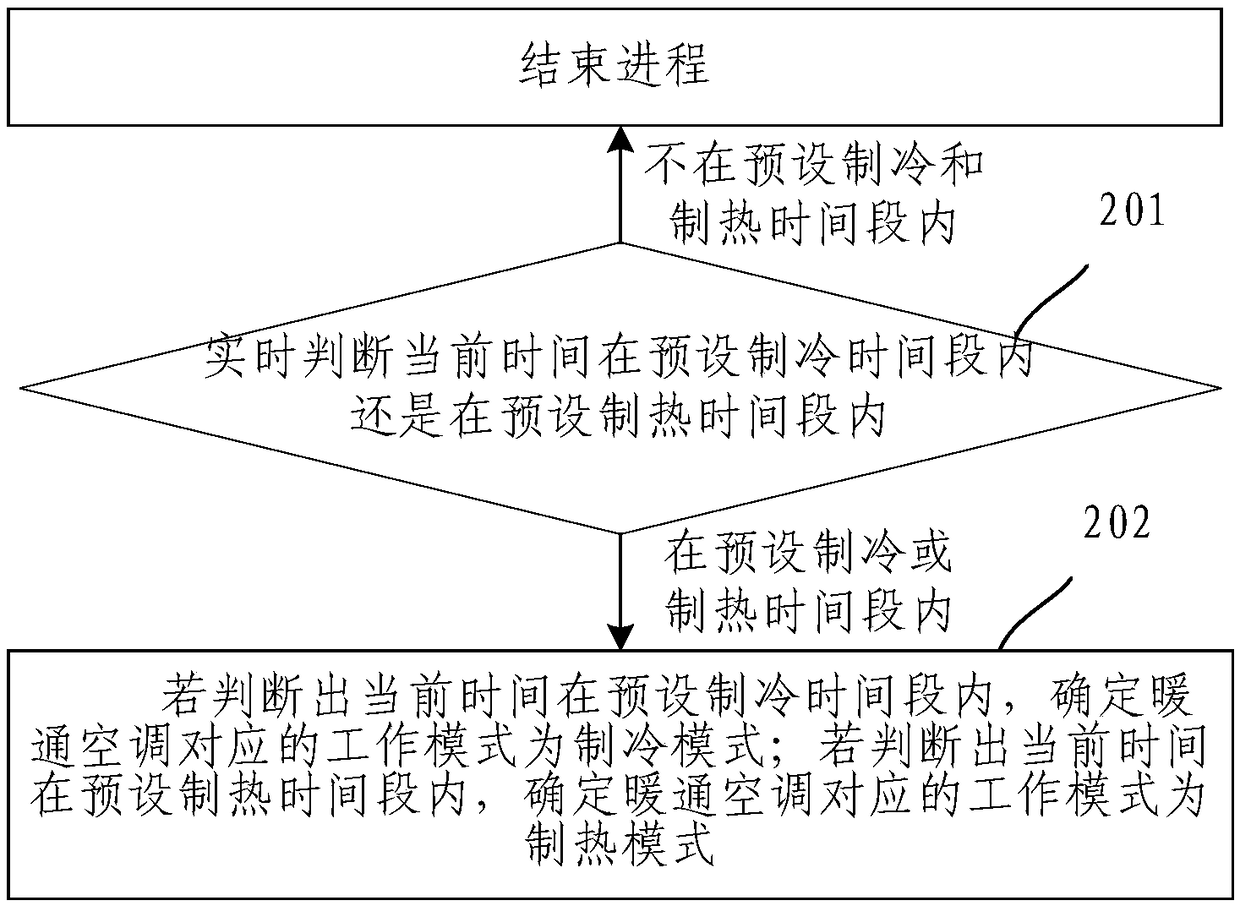
[0097] The controller 102 is used to judge in real time whether the current time is within the preset cooling time period or within the preset heating time period;

[0098] If it is determined that the current time is neither within the preset cooling time period nor within the preset heating time period, the controller 102 is also used to end the process;

[0099] If it is determined that the current time is within the preset cooling time period, the controller 102 is further configured to determine that the correspo...

Embodiment 2

[0116] Embodiment 2 of the present invention provides another automatic temperature control system based on the automatic temperature control system provided in Embodiment 1. The structural diagram of the system can be found in figure 1 , HVAC system 103, including at least one heat pump 1031, at least one supplementary water pump 1032, at least one circulation pump 1033, end wind disk system 1034, return water main pipe 1035 and water outlet main pipe 1036, wherein:

[0117] At least one heat pump 1031, at least one make-up water pump 1032, at least one circulation pump 1033 and end air disk system 1034 are respectively connected to the controller 102;

[0118] The system also includes a pressure sensor 104, which is installed on the water return main pipe 1035 and connected with the controller 102; then

[0119] The controller 102 is also used for:

[0120] Obtain the first pressure value in the water return main pipe 1035 in real time by the pressure sensor 104;

[0121] ...

Embodiment 3

[0149] Embodiment 3 of the present invention provides another automatic temperature control system based on the automatic temperature control system provided in Embodiment 2. The structural diagram of the system can be found in figure 1 , the system also includes a pipeline temperature sensor 107 ( figure 1 Only schematically draw the installation position of the pipeline temperature sensor 107 in the figure, and do not draw the exact position), which is installed on the water outlet main pipe and connected with the controller 102; then

[0150] The controller 102 is also used for:

[0151] When the HVAC system 103 turns on the cooling mode or the heating mode, the first outdoor temperature is acquired through the outdoor temperature sensor 101 according to a preset time interval;

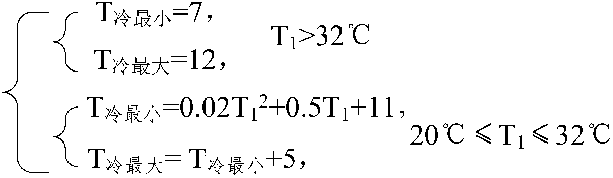
[0152] According to the first outdoor temperature, and according to the calculation formula of the preset temperature range, determine the first temperature range that the water in the water outle...


PUM


Abstract

The invention discloses an automatic temperature control system and method, and belongs to the field of temperature control. The system comprises an outdoor temperature sensor, a controller, a heatingventilation air conditioning system and an outdoor temperature sensor which is arranged outdoors; the controller is connected with the outdoor temperature sensor and the heating ventilation air conditioning system and used for judging that the current time is within the preset refrigeration time period or in the preset heating time period in real time; if it is judged that that the current time is neither within the preset refrigeration time period nor in the preset heating time, the controller is further used for stopping the process; if it is judged that that the current time is within thepreset refrigeration time period, the controller is further used for determining the working mode of the heating ventilation air conditioning system to be in the refrigeration mode; and if it is judged that that the current time is within the preset heating time period, the controller is further used for determining the working mode of the heating ventilation air conditioning system to be in the heating mode. Manual judgment is not needed, the controller can conduct automatic judgment, manpower resources are saved, and the efficiency of the method of the determining work is improved.

Description

technical field [0001] The invention relates to the field of temperature control, in particular to an automatic temperature control system and method. Background technique [0002] In the prior art, a common HVAC system generally includes at least one heat pump, at least one make-up water pump, at least one circulation pump, terminal air coil system, water return main pipe and water outlet main pipe. [0003] When using the HVAC system for cooling or heating, staff are required to judge whether to turn on the cooling mode or the heating mode according to actual needs, and the manual determination method is inefficient. Contents of the invention [0004] The purpose of the embodiments of the present invention is to provide an automatic temperature control system and method to solve the problem of low efficiency of the method for determining the working mode of the HVAC system in the prior art. [0005] In order to achieve the above object, the technical solution of the emb...

Claims


Application Information

Patent Timeline
Patent Type & Authority Applications(China)
IPC IPC(8): F24F11/00F24F11/89F24F110/00
CPCF24F11/00F24F11/89F24F2110/00
Inventor 郭梁
Owner 贵州鸿巨燃气热力工程有限公司
Why Eureka
Try Eureka