Chip drying mechanism

A drying mechanism and chip technology, which is applied in the direction of dryers, drying, local stirring dryers, etc., can solve the problems that water vapor is not easily emitted, affecting processing efficiency and processing quality, so as to reduce the impact of water vapor and ensure Processing quality, the effect of avoiding aging

Active Publication Date: 2019-01-04
泸州龙芯微科技有限公司
View PDF6 Cites 3 Cited by
  • Summary
  • Abstract
  • Description
  • Claims
  • Application Information

AI Technical Summary

Problems solved by technology

[0005] The present invention intends to provide a chip drying mechanism to solve the problem that the water vapor caused by t

Method used


Image

  • Chip drying mechanism
  • Chip drying mechanism
  • Chip drying mechanism

Examples


Embodiment Construction

[0022] The present invention will be described in further detail below by means of specific embodiments:

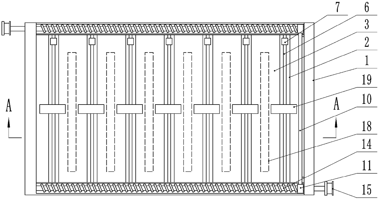
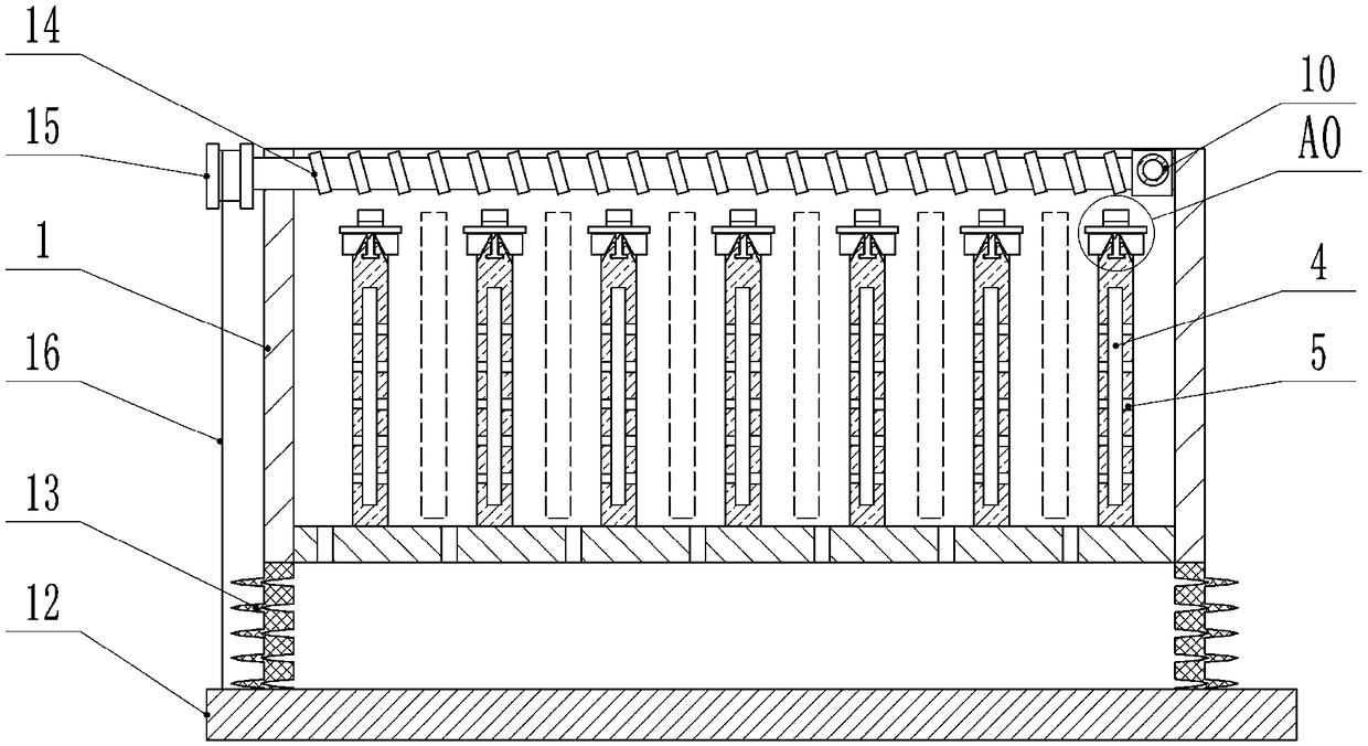
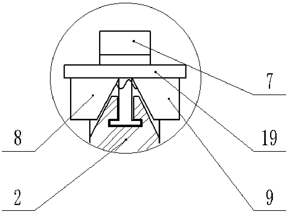
[0023] The reference signs in the drawings of the description include: drying tank 1, partition plate 2, slot 3, cavity 4, heat release hole 5, chute 6, slider 7, first wedge 8, second wedge 9. Negative pressure tube 10, sliding sleeve 11, bottom plate 12, telescopic tube 13, lead screw 14, reel 15, stay cord 16, telescopic plate 17, disc body 18, connecting plate 19.

[0024] Example figure 1 with figure 2 Commonly shown: chip drying mechanism, including a drying tank 1 with an upward opening, in which there are seven parallel and transversely distributed partitions 2, and there are gaps between adjacent partitions 2 to form slots 3 , the seven-side partition 2 forms a total of six slots 3 for placing and drying the disc body 18 with chips mounted on six sides. Cavities 4 are provided in the partitions 2, and heat sources are installed in the cavities 4. The heat sou...


PUM


Abstract

The invention relates to the field of chip drying equipment, and discloses a chip drying mechanism. The chip drying mechanism comprises a drying groove opened up; at least two separation plates, transversely distributed in parallel, are arranged in the drying groove; gaps are formed in the adjacent separation plates to form slots; cavities are formed in the separation plates; heat sources are mounted in the cavities; heat releasing holes communicating with the slots are formed in the walls of the cavities; and the separation plates are provided with fixing units for maintaining the distances from chip disc bodies to the separation plates. The chip drying mechanism can solve the quality of influence on the machining efficiency and the machining quality by difficult dissipation of water vapor due to a traditional laminate drying structure.

Description

technical field [0001] The invention relates to the field of chip drying equipment, in particular to a chip drying mechanism. Background technique [0002] When processing chips, since chips are usually small in size, in order to prevent chips from being lost during processing, the chips are currently uniformly fixed on a larger disk for processing, and the disk acts as a carrier for the chip. Provide convenience for chip movement and processing. [0003] In the process of processing the chip, after the chip is etched, the surface of the chip needs to be cleaned, so as to prevent impurities from accumulating on the chip and affecting the processing quality of the chip. After cleaning, the chip needs to be dried to avoid corrosion of the chip structure caused by residual moisture on the chip. [0004] The existing drying devices for chips are usually stacked, that is, the etched and cleaned disks are stacked layer by layer and placed in a drying box for drying. Although the...

Claims


Application Information

Patent Timeline
IPC IPC(8): F26B9/06F26B21/00F26B25/08F26B25/00
CPCF26B9/06F26B21/004F26B25/005F26B25/08
Inventor 黄晓波
Owner 泸州龙芯微科技有限公司
Why Eureka
Try Eureka