Method and device of reaction cup movement path control

A motion path and control method technology, applied in the direction of analyzing materials, instruments, etc., can solve the problems of stuck pipes, falling into through holes, etc., and achieve the effect of reducing volume, preventing stuck pipes, and preventing stuck pipes.

Active Publication Date: 2019-01-04
MACCURA MEDICAL INSTR CO LTD
View PDF8 Cites 0 Cited by
  • Summary
  • Abstract
  • Description
  • Claims
  • Application Information

AI Technical Summary

Problems solved by technology

In the cuvette loading device with this structure, in the process of loading cuvettes, it is easy for the cuvette behind the first cuvette to fall into the through hole before the switch assembly is closed, so that multiple reactions The cups are piled up between the next station under the through hole and the position of the through hole, which prevents the switch assembly from closing, resulting in tube jamming

Method used


Image

  • Method and device of reaction cup movement path control
  • Method and device of reaction cup movement path control
  • Method and device of reaction cup movement path control

Examples


Embodiment Construction

[0048] In order to better understand the present invention, the method and device for controlling the movement path of cuvettes according to the embodiments of the present invention will be described in detail below with reference to the accompanying drawings.

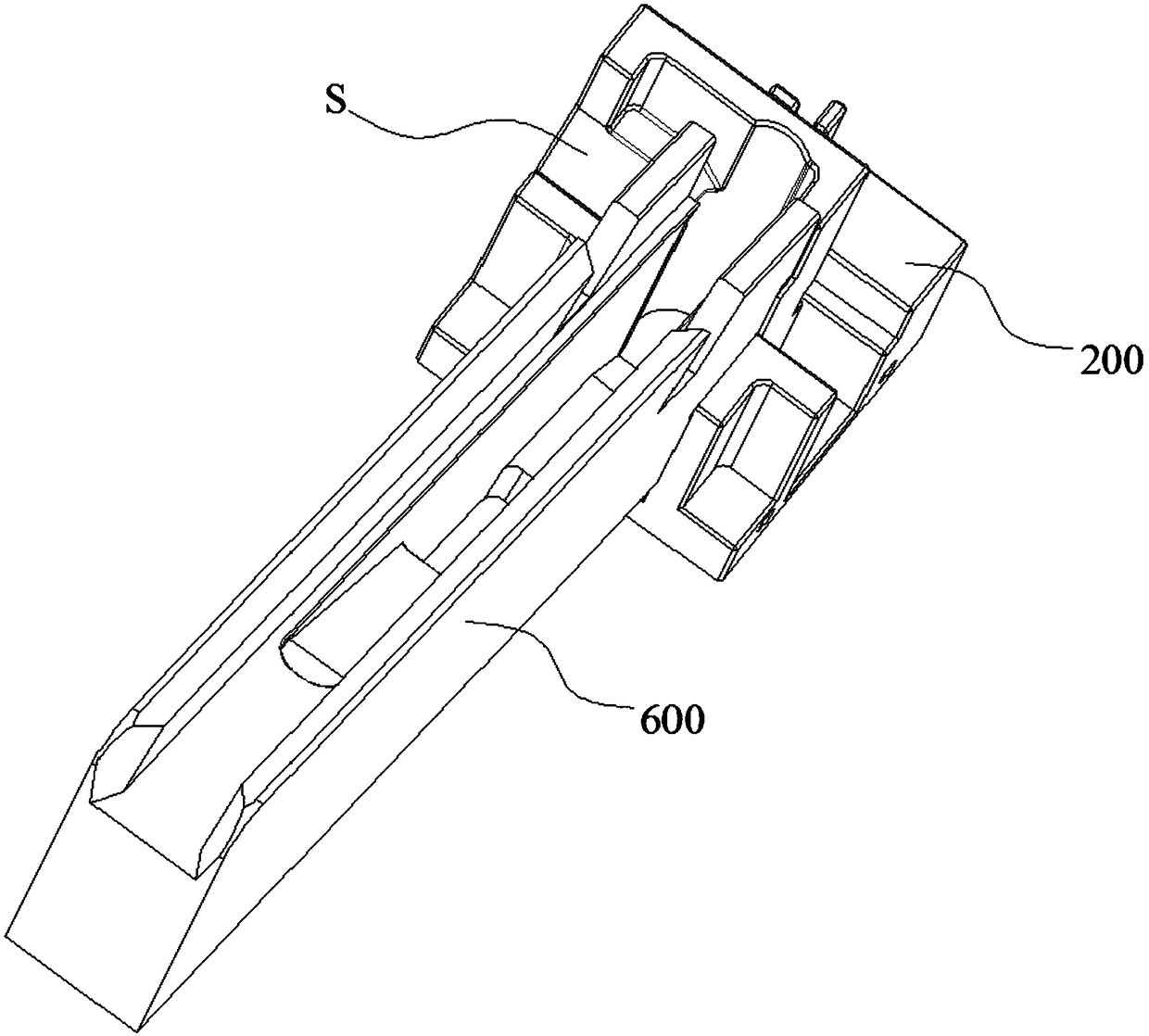
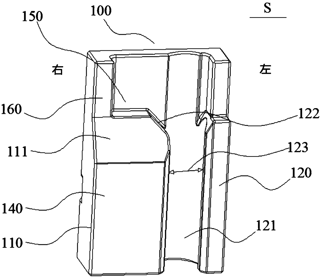
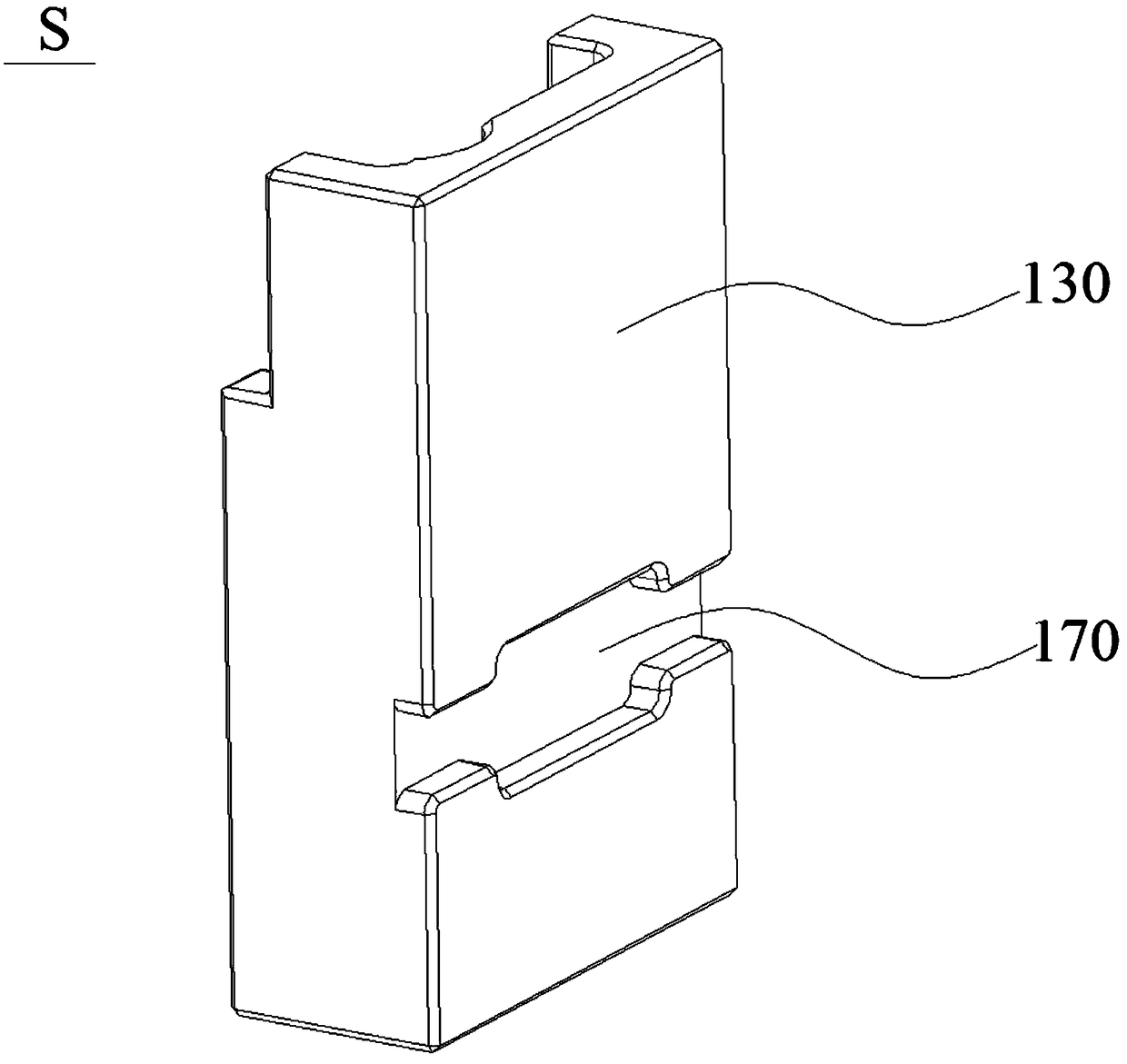
[0049] like Figure 1 to Figure 12 As shown, the cuvette pusher S of this embodiment includes a pusher body 100, and the pusher body 100 is provided with a cup stopper 110 and a cup guide 120, and the cup stopper 110 is used to stop the For the cuvette N of W, the cup guide part 120 is used to guide the single cuvette N at the waiting station W to the next station,

[0050] The push block body 100 can move in the push block movement channel 201 on the base 200. By moving the push block body 100, the cup body blocking part 110 or cup body guide part 120 on the push block body 100 can be connected to the waiting station W Docking, the cuvette located at the waiting station W can be blocked by the cup body blocking part ...


PUM


Abstract

The invention provides a method and device of reaction cup movement path control, wherein the method comprises the following steps: in response to a demand of adding a reaction cup, the reaction cup pusher is controlled by a controller to move to a second ultimate limit state, so that a blocking part of a cup body of the reaction cup pusher is relieved from blocking a first reaction cup positionedat a waiting station, the first reaction cup positioned at the waiting station enters a cup body guiding channel of the reaction cup pusher, the controller controls the reaction cup pusher to move toa first ultimate limit state, the cup guiding channel is communicated with the next station, so that the first reaction cup entering the guiding channel of the cup body is conveyed to the next station, the reaction cup next to the first reaction cup arranged in a conveying trough of the reaction cup into the waiting station, and the reaction cup entering the waiting position is blocked at the waiting station by the blocking part of the cup. By the method, only one reaction cup can be transported from the waiting station to the next station at one time, and the control flow of the component atthe next station can be simplified.

Description

technical field [0001] The invention relates to the field of in vitro diagnosis, in particular to a method and device for controlling the motion path of a cuvette. Background technique [0002] In the in vitro diagnostic analyzer, the cuvettes are transported from the cuvette silo to the loading channel through the conveyor chain, lined up in the loading channel and sequentially pass through the loading device to enter the next designated position, such as a reagent tray. A through hole corresponding to the outlet of the loading channel is provided on the traditional loading device, and a switch assembly is provided on the through hole to open and close the through hole. When the cuvette needs to be loaded, the through hole is opened and closed by the switch assembly, so that The first cuvette at the position falls into the through hole. In the cuvette loading device with this structure, in the process of loading cuvettes, it is easy for the cuvette behind the first cuvette...

Claims


Application Information

Patent Timeline
Patent Type & Authority Applications(China)
IPC IPC(8): G01N35/04
CPCG01N35/04G01N2035/0489G01N2035/0462
Inventor 陈建波张业祥李浩
Owner MACCURA MEDICAL INSTR CO LTD
Why Eureka
Try Eureka