
Timing circuit, readout circuit, scintillation detector and timing method

A technology of scintillation detectors and timing circuits, which is applied in the field of readout circuits, scintillation detectors and timing, and timing circuits. It can solve the problems that timing signals increase the system processing burden and increase the complexity of subsequent processing.

Inactive Publication Date: 2020-07-28
INST OF HIGH ENERGY PHYSICS CHINESE ACAD OF SCI
View PDF7 Cites 0 Cited by
  • Summary
  • Abstract
  • Description
  • Claims
  • Application Information

AI Technical Summary

Problems solved by technology

This processing method is relatively simple, but the false triggering of timing signals by noise and useless small-amplitude signals will increase the processing burden of the system and increase the complexity of subsequent processing.

Method used


Image

  • Timing circuit, readout circuit, scintillation detector and timing method
  • Timing circuit, readout circuit, scintillation detector and timing method
  • Timing circuit, readout circuit, scintillation detector and timing method

Examples


Embodiment Construction

[0028] Example embodiments will now be described more fully with reference to the accompanying drawings. Example embodiments may, however, be embodied in many forms and should not be construed as limited to the examples set forth herein; rather, these embodiments are provided so that this disclosure will be thorough and complete and fully convey the concept of example embodiments to those skilled in the art.

[0029] Furthermore, the described features, structures, or characteristics may be combined in any suitable manner in one or more embodiments. In the following description, numerous specific details are provided in order to give a thorough understanding of embodiments of the invention. However, those skilled in the art will appreciate that the technical solutions of the present invention may be practiced without one or more of the specific details, or other methods, components, means, steps, etc. may be employed. In other instances, well-known methods, apparatus, implem...


PUM


Abstract

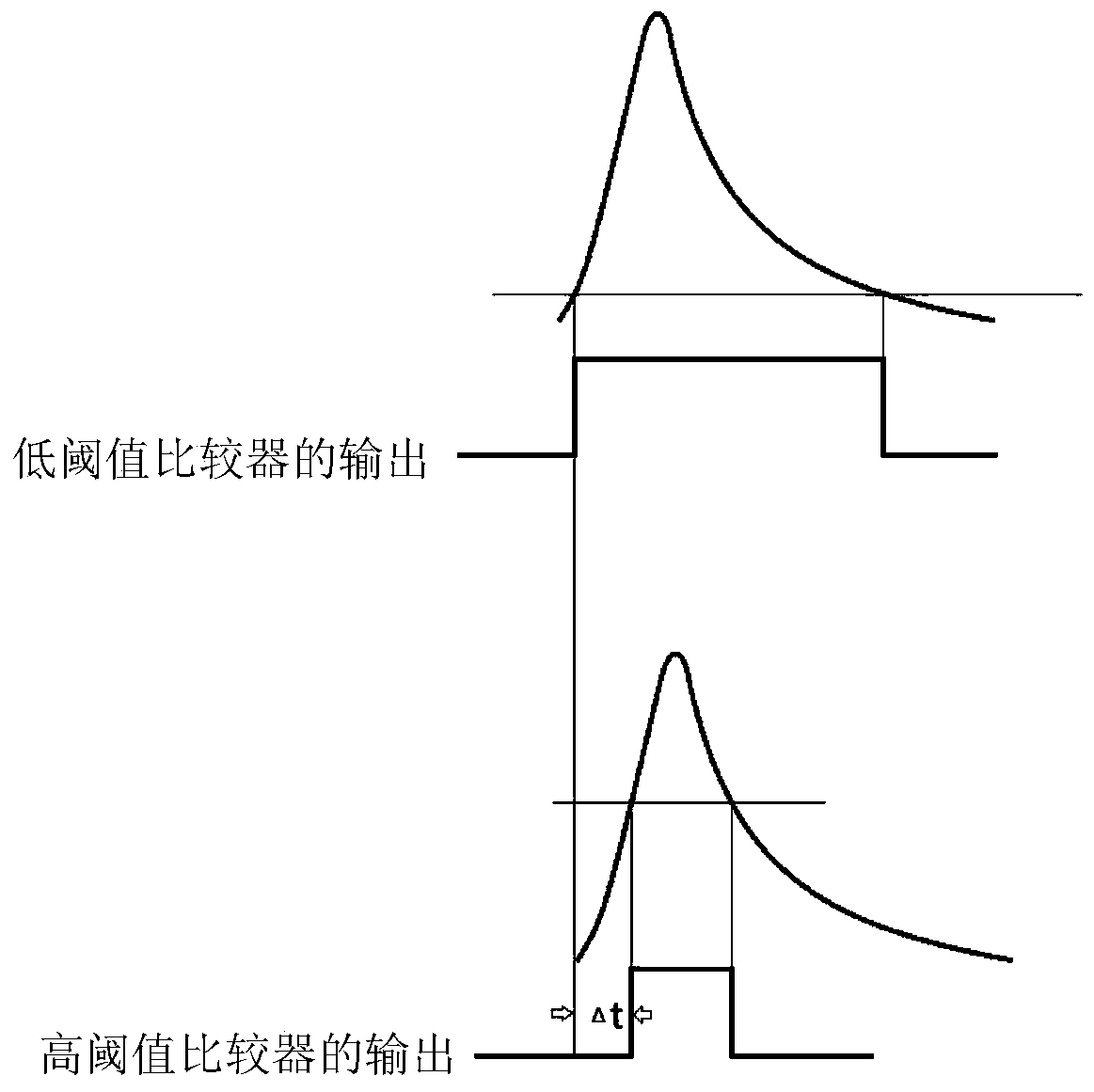
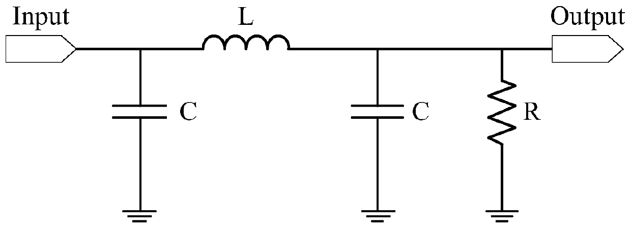
The invention provides a timing circuit, a readout circuit, a scintillation detector and a timing method. The timing circuit comprises a signal source, a first comparator, a second comparator, a thirdcomparator, a first trigger circuit and a second trigger circuit; signals generated by the signal source are divided into a first path of signals and a second path of signals; the input end of the first comparator receives the first path of signals; the input end of the second comparator receives the second path of signals; the comparison threshold of the second comparator is greater than the comparison threshold of the first comparator; the input end of the third comparator is connected to the output end of the first comparator; the input end of the first trigger circuit is connected with the output end of the third comparator; the input end of the second trigger circuit is connected to the output end of the second comparator; and the output end of the second trigger circuit is used fortransmitting door-opening signals to the first trigger circuit so as to trigger the first trigger circuit to output timing signals. With the technical schemes of the invention adopted, the simplicityand feasibility of the timing circuit are ensured, and the requirement of timing precision can be satisfied.

Description

technical field [0001] The invention relates to the technical field of timing, in particular to a timing circuit, a readout circuit, a scintillation detector and a timing method. Background technique [0002] A scintillation detector is a commonly used detector in the field of ray detection, and is usually composed of a scintillator, a photoelectric conversion device, and a readout circuit. When the ray is incident and interacts with the scintillator, the energy will be deposited in the scintillator and then converted into scintillation light. The scintillation light is collected by the photoelectric conversion device and converted into an electrical signal, and then processed by the readout circuit to obtain the incident ray related information. In many cases, technicians need to accurately measure the time information of rays, such as positron lifetime spectrometer measurement, time of flight-Positron Emission Computed Tomography (TOF-PET), etc. The higher the accuracy of...

Claims


Application Information

Patent Timeline
Patent Type & Authority Patents(China)
IPC IPC(8): G01T1/208H03K17/28
CPCG01T1/208H03K17/28
Inventor 唐浩辉李道武章志明王英杰柴培杨明洁魏龙
Owner INST OF HIGH ENERGY PHYSICS CHINESE ACAD OF SCI
Learn More