
Eureka
For R&D, Eureka makes reading and utilizing patents & technical documents easy.
Eureka AIR
Designed for self-driven R&D workflows. Generate viable solutions, solve complex R&D challenges, empower your innovation with AI.

Eureka Materials
Designed for material experts only. Revolutionize your material R&D, from search, analyze, to developing new materials.

TechResearch
Generate reliable direction feasibility study reports for your R&D in just a few steps.

TechSeek
Discover and master advanced knowledge NOW. Basics, ideas, possibilities, all at once.

TechMind
As an expert in R&D Theories, TechMind can generates customized viable solutions instantly.

TechRisk
Analyze your overall solution with one click, know your potential R&D risks in advance.

TechMonitor
Get weekly tech updates, stay abreast of the latest tech innovations and key insights.
Lens unit and manufacturing method
A lens unit and lens technology, applied in optical components, installation, optics, etc., can solve problems such as deformation of the lens receiving surface, relative position deviation and height deviation between the mirror base and the glass lens, and achieve the effect of improving optical performance
- Summary
- Abstract
- Description
- Claims
- Application Information
AI Technical Summary
Problems solved by technology
Method used
Image

Examples
no. 1 approach
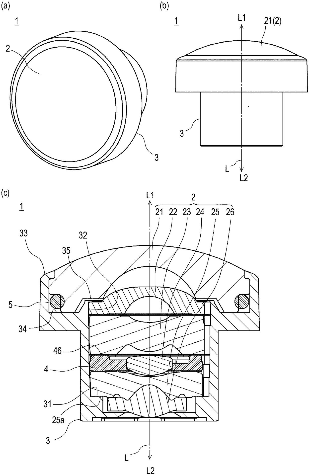
[0080] figure 1 shows the whole of the lens unit 1 of the present embodiment, figure 1 (a) is a stereogram, figure 1 (b) is the main view, figure 1 (c) is a longitudinal sectional view.
[0081] The lens unit 1 is a lens unit incorporated in a vehicle-mounted peripheral monitoring camera, a monitoring camera, an intercom system, and the like. In addition, the "object side L1" and "image side L2" in the present invention refer to the object side and the image side in the optical axis L direction, and the "optical axis direction" refers to a direction parallel to the optical axis L.
[0082] (the whole frame)
[0083] The lens unit 1 includes: a wide-angle lens 2 composed of a plurality of lenses; and a lens barrel 3 that accommodates the wide-angle lens 2 . The wide-angle lens 2 is composed of a first lens 21, a second lens 22, a third lens 23, a fourth lens 24, a fifth lens 25, and a sixth lens 26, which are closely arranged along the optical axis L from the object side L...
no. 2 approach
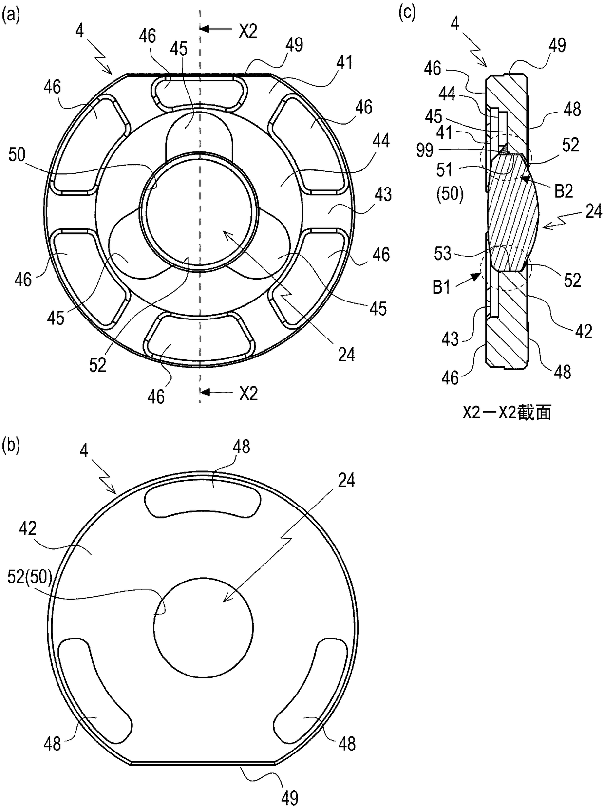
[0137] This embodiment shows a modified example of the shape of the mirror holder 4 of the first embodiment. Figure 9 It is a figure which shows the lens holder 104 and the 4th lens 24 which were press-fitted in this embodiment, and shows the state before reinforcement with an adhesive agent. Figure 9 (a) is a top view, Figure 9 (b) is a side view, Figure 9 (c) is Figure 9 X3-X3 sectional view of (a). Here, configurations different from those of the mirror holder 4 of the first embodiment will be mainly described.
[0138] Like the mirror mount 4 of the first embodiment, the object-side flat surface 141 includes an outer-edge-side flat surface 143 and an inner-edge-side flat surface 144 , and a cylindrical portion 150 is formed at the center thereof. In the same positions as in the first embodiment, the adhesive groove 145 on the inner edge side plane 144 and the press-fitting portion 153 on the cylindrical side surface 151 are formed at three places, respectively.
...
PUM
 Abstract
Description
Claims
Application Information
 - R&D Engineer
- R&D Manager
- IP Professional
- Industry Leading Data Capabilities
- Powerful AI technology
- Patent DNA Extraction
Browse by: Latest US Patents, China's latest patents, Technical Efficacy Thesaurus, Application Domain, Technology Topic, Popular Technical Reports.
© 2024 PatSnap. All rights reserved.Legal|Privacy policy|Modern Slavery Act Transparency Statement|Sitemap|About US| Contact US: help@patsnap.com