Method, device, and terminal for determining transmission power

A technology of sending power and determining method, which is applied in the field of communication, can solve problems such as inaccurate calculation results, and achieve the effect of high reliability

Active Publication Date: 2022-04-05
ZTE CORP
View PDF13 Cites 0 Cited by
  • Summary
  • Abstract
  • Description
  • Claims
  • Application Information

AI Technical Summary

Problems solved by technology

[0007] Embodiments of the present invention provide a method, device, and terminal for determining transmit power, which are at least used to solve the problem in related technologies. In the NR field, the traditional calculation method in the LTE field is used to calculate the transmit power for uplink transmission, resulting in incorrect calculation results. exact question

Method used


Image

  • Method, device, and terminal for determining transmission power
  • Method, device, and terminal for determining transmission power
  • Method, device, and terminal for determining transmission power

Examples


Embodiment 1

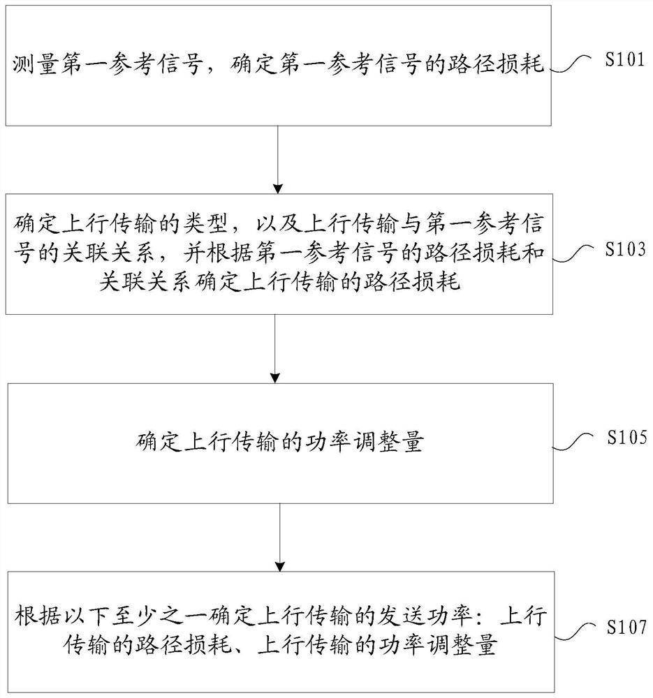
[0109] In an embodiment of the present invention, a method for determining transmission power is provided. figure 1 is a flow chart of an optional method for determining transmission power according to an embodiment of the present invention. Such as figure 1 As shown, an optional flow of the method for determining the transmission power includes:

[0110] Step S101, measure the first reference signal, and determine the path loss of the first reference signal;

[0111] Step S103, determining the type of uplink transmission, and the association relationship between the uplink transmission and the first reference signal, and determining the path loss of the uplink transmission according to the path loss and the association relationship of the first reference signal;

[0112] Step S105, determining the power adjustment amount for uplink transmission;

[0113] Step S107, determining the transmit power of the uplink transmission according to at least one of the following: a path ...

Embodiment 2

[0139] An optional device for determining transmission power is also provided in this embodiment, and the device is used to implement the above embodiments and preferred implementation modes, and what has already been described will not be repeated. As used below, the term "module" may be a combination of software and / or hardware that realizes a predetermined function. Although the devices described in the following embodiments are preferably implemented in software, implementations in hardware, or a combination of software and hardware are also possible and contemplated.

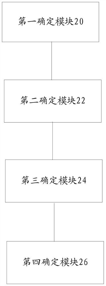
[0140] According to an embodiment of the present invention, there is also provided a device for implementing the above method for determining transmission power, which is applied to a terminal. figure 2 is a structural block diagram of an optional device for determining transmission power according to an embodiment of the present invention. Such as figure 2 As shown, the device includes:

[0141] The f...

Embodiment 3

[0177] In order to better understand the technical solutions of the present invention, the embodiments of the present invention are further described through the following specific implementation methods.

[0178] In a wireless communication system, in order to reduce the power consumption of the transmitting device and reduce the interference caused by unnecessary high-power transmission to other transmissions, it is necessary to control the transmission power. The size of the communication range, the maximum transmission power and reception sensitivity of the transceiver equipment on both sides of the communication, the modulation and coding method and rate of the data, the working frequency band, the bandwidth occupied by the transmission and other factors will affect the transmission power. Generally, it is necessary to use a lower transmission power as much as possible under the condition that the received signal quality requirements of the receiving end are met.

[0179]...


PUM


Abstract

The present invention provides a transmission power determination method, device, and terminal, wherein the method includes: measuring the first reference signal, determining the path loss of the first reference signal; determining the type of uplink transmission, and the relationship between the uplink transmission and the first reference signal Signal correlation, and determine the path loss of the uplink transmission according to the path loss of the first reference signal and the correlation; determine the power adjustment amount of the uplink transmission; determine the transmit power of the uplink transmission according to at least one of the following: The path loss of uplink transmission and the power adjustment amount of uplink transmission. It solves the problem that in the related art, in the NR field, the traditional calculation method in the LTE field is used to calculate the transmission power of the uplink transmission, which leads to inaccurate calculation results.

Description

technical field [0001] The present invention relates to the communication field, in particular, to a method and device for determining transmission power, and a terminal. Background technique [0002] At present, a new generation of wireless communication (new radio, NR for short) technology is being formulated. As the fifth generation of mobile communication system, this technology needs to support an unprecedented number of different types of application scenarios, and also needs to support both traditional frequency bands and high frequency bands. And the beam mode brings great challenges to the design of power control. [0003] The sounding reference signal SRS (Sounding Reference Signal, referred to as SRS) transmission power in the long-term evolution technology LTE is determined by the relevant parameters of the physical uplink shared channel (Physical Uplink Shared Channel, referred to as PUSCH). Configure related parameters of SRS. [0004] Generally, the transmis...

Claims


Application Information

Patent Timeline
Patent Type & Authority Patents(China)
IPC IPC(8): H04W52/14H04W52/24H04W52/32H04W52/36H04W56/00
CPCH04W52/146H04W52/242H04W52/322H04W52/367H04W56/0005H04W52/325H04W52/42
Inventor 姚珂高波王瑜新蒋创新鲁照华
Owner ZTE CORP
Why Eureka
Try Eureka