
Pump Can Kits for Beverage Cans

A technology of beverage cans and pump cans, which is applied in the field of pump can sets, and can solve the problems that functional correlation cannot be simply converted

Active Publication Date: 2021-09-03
EMSA
View PDF6 Cites 0 Cited by
  • Summary
  • Abstract
  • Description
  • Claims
  • Application Information

AI Technical Summary

Problems solved by technology

For aesthetic reasons, an essentially flat structural form is thus expected, but this cannot be easily converted due to the functional dependencies introduced

Method used


Image

  • Pump Can Kits for Beverage Cans
  • Pump Can Kits for Beverage Cans
  • Pump Can Kits for Beverage Cans

Examples


Embodiment Construction

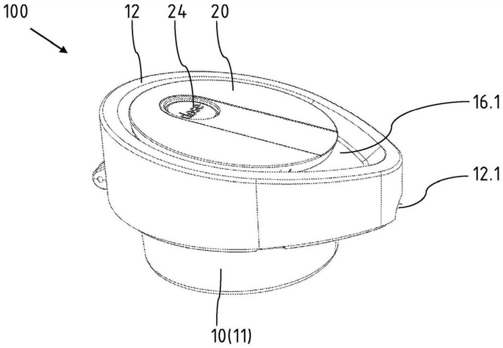
[0022] figure 1 The pump canister set 100 is shown from the outside in a perspective view. The housing 10 has, in addition to the housing upper part 12 , a lower part 11 which is slightly reduced in diameter. The housing upper part 12 is designed to be slightly lowered to the right—thus where the discharge pipe of the riser unit (not shown) cooperating with the pump tank set 100 is arranged. Overall, a flat and aesthetically appealing configuration of the pump canister set 100 is achieved.

[0023] exist figure 1 In the region on the right in , at the bottom, a cutout 12 . 1 can be seen on the overhang of the housing upper part 12 , which accommodates the outlet pipe. A recess 16 . Finished evenly. The button 24 can be actuated via a cutout in the pump lever 20 .

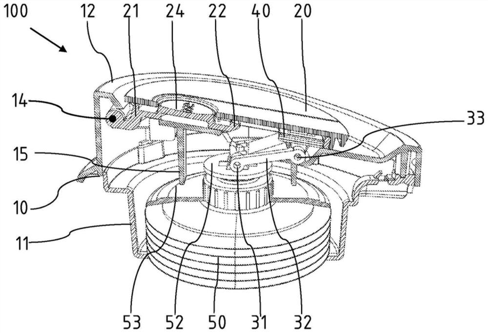
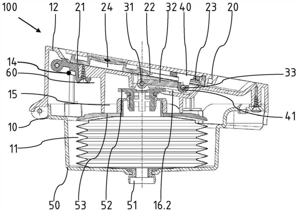
[0024] figure 2 The pump tank set 100 is likewise shown in perspective and in the transport position, wherein all components are shown in cross-section except for the pump assembly including the pump bellows...


PUM


Abstract

The invention relates to a pump can set (100) for beverage cans, comprising: a casing (10); a pump bellows (50) arranged in said casing (10), said pump bellows The box has a riser connection on the lower side and a head element (52) on the upper side. Furthermore, the pump-tank set comprises a pump lever (20) supported on said housing (10) via a pivot joint (14), said pump lever being connected to The head element (52) is connected. The pump tank set (100) is characterized in that the transfer element is configured as a double-joint lever (32) with an upper joint (33) and a lower joint (31), wherein the upper joint (33) is movably held by It is supported in or on the pump lever (20), and wherein the lower joint (31) is connected to the upper side of the pump bellows (50).

Description

technical field [0001] The invention relates to a pump can set for beverage cans having the features of the preamble of claim 1 . Background technique [0002] A pump canister with a pump canister set is shown in DE 203 02 345 U1. With the aid of the pump canister set, pre-prepared hot or cold beverages can be filled via the riser and the discharge connection into the container positioned next to the canister. For this purpose, the pump lever is raised such that the multi-articulated transmission element is positioned in the deployed position above the pump bellows. The pump lever pivotally supported on the housing is then pressed down, thereby compressing the pump bellows and increasing the pressure in the tank. The liquid stored in the container is discharged into the outlet through the riser. When moving downwards, the pose of the transmission element is changed slightly, but remains in a substantially upright pose. In order to be able to push a sufficient liquid volu...

Claims


Application Information

Patent Timeline
Patent Type & Authority Patents(China)
IPC IPC(8): A47J41/00
CPCA47J41/0033
Inventor 马卡斯·赫尔布
Owner EMSA
Learn More