Integrated barrel type vertical-shaft stirring machine adopting dual-wormwheel and single-worm transmission

A technology of worm drive and double worm gear, which is applied in the direction of cement mixing equipment, clay preparation equipment, chemical instruments and methods, etc., can solve the problem of inability to meet the rigidity requirements of mixing large-volume mixture, the shaft end seal cannot be effectively solved, and the discharge port The problem of sticking and clogging can be solved, and the effect of simple structure, increased rigidity and increased mixing area can be achieved.

Pending Publication Date: 2019-01-08
CHANGAN UNIV
View PDF0 Cites 2 Cited by
  • Summary
  • Abstract
  • Description
  • Claims
  • Application Information

AI Technical Summary

Problems solved by technology

[0003] Most of the concrete mixers commonly used now are in the form of horizontal shafts, and the problem of shaft end sealing has not been effectively solved. When mixing highly viscous mixtures, there is a problem that the discharge port is stuck and blocked and cannot be discharged normally.
However, most of the existing vertical concrete mixer models are single vertical shaft, with low mixing efficiency and long mixing time, which are only suitable for the production of concrete prefabricated parts
The transmission device of the common double vertical shaft model has a complex structure, takes up a lot of space, the transmission effect is unstable, and the unloading is also laborious. The connection structure of the mixing arm cannot meet the rigidity requirements for mixing large-volume mixtures.

Method used


Image

  • Integrated barrel type vertical-shaft stirring machine adopting dual-wormwheel and single-worm transmission
  • Integrated barrel type vertical-shaft stirring machine adopting dual-wormwheel and single-worm transmission
  • Integrated barrel type vertical-shaft stirring machine adopting dual-wormwheel and single-worm transmission

Examples


Embodiment Construction

[0036] The present invention is further described below in conjunction with accompanying drawing:

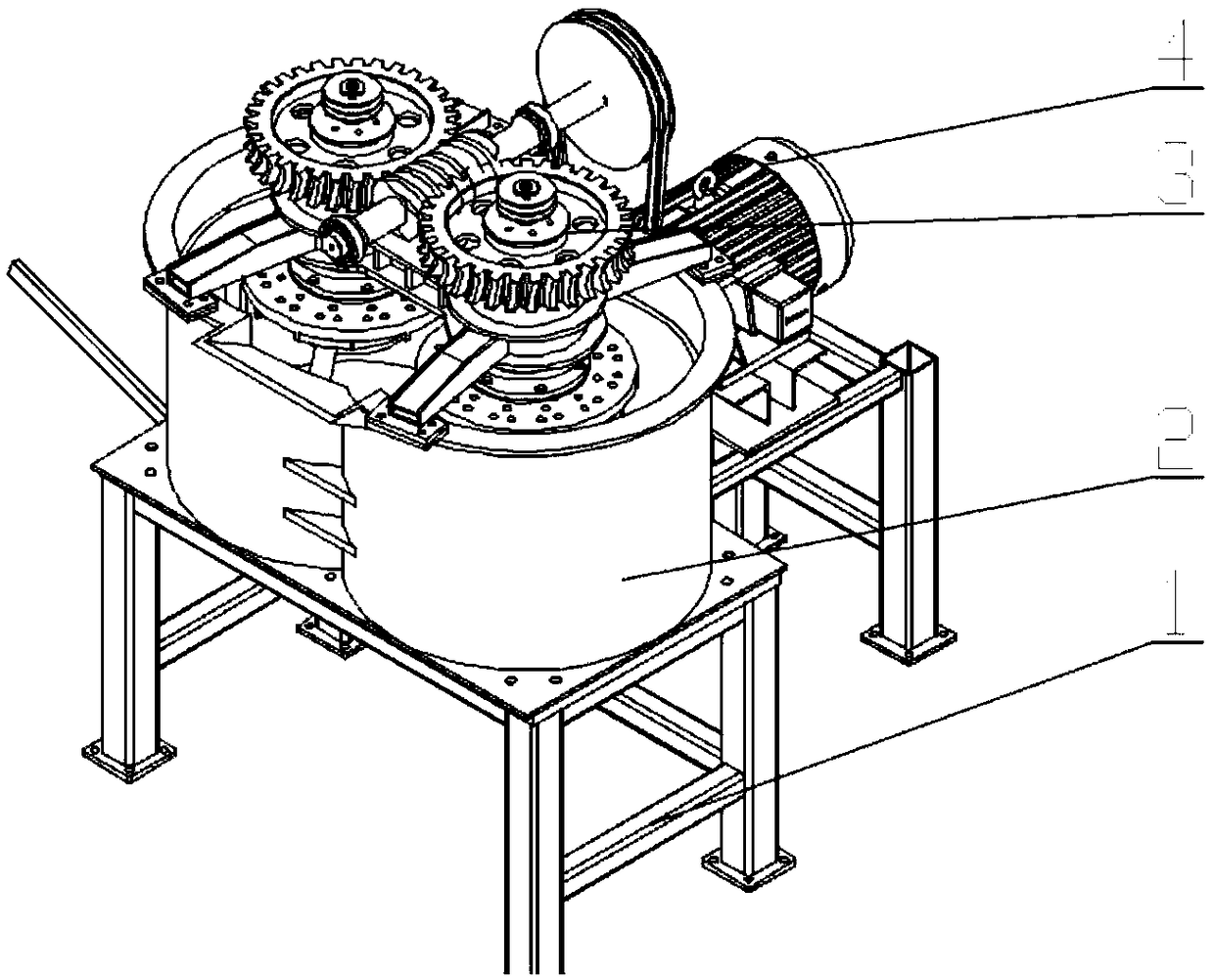
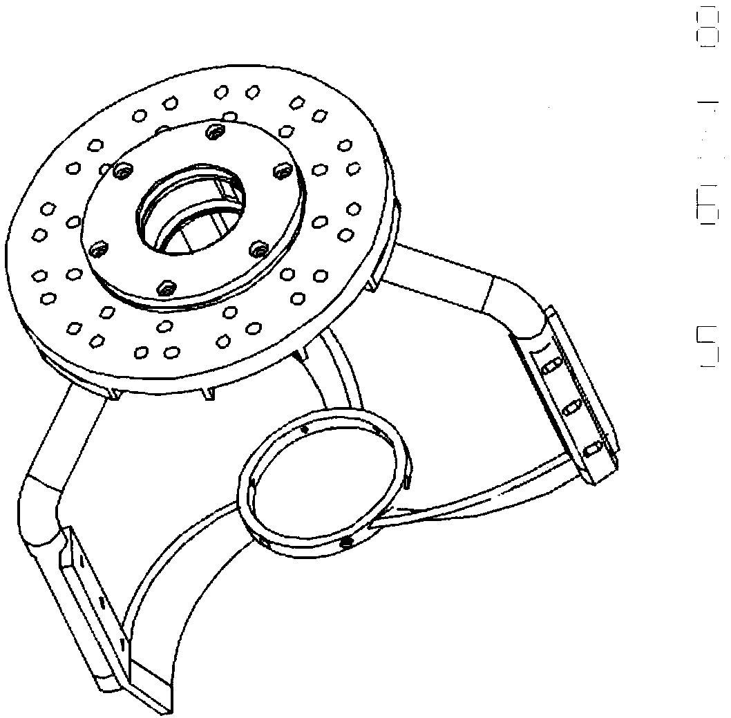
[0037] see Figure 1-Figure 4 , a dual-worm gear and single-worm drive conjoined cylinder vertical shaft mixer, comprising a supporting base 1, a conjoined mixing drum 2 is connected to the supporting base 1, and two reversely rotating stirring devices are arranged in the conjoined mixing drum 2 , also includes a driving device 4 and a double worm gear single worm transmission device connecting the driving device 4 and the stirring device;

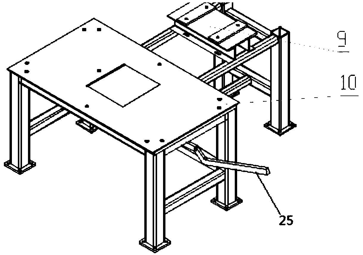
[0038] Several rubber shock-absorbing gaskets are installed at the bottom of each support leg of the support chassis 1, and a shock-absorbing rubber frame is placed above the front part of the support chassis 1 so as to be connected with the bottom plate 10 of the conjoined mixing drum 2, and the rear part of the support chassis 1 The driving motor seat 9 is fixed on the top, and the driving motor seat 9 is formed by tailor-welding of horiz...


PUM


Abstract

An integrated barrel type vertical-shaft stirring machine adopting dual-wormwheel and single-worm transmission comprises a supporting underframe, a stirring barrel, a dual-wormwheel and single-worm transmission device, a driving device, and stirring devices, wherein the stirring barrel and the driving device are both arranged on the supporting underframe; the stirring devices are arranged in the stirring barrel; the dual-wormwheel and single-worm transmission device is arranged on the stirring devices; and the driving device is connected with the dual-wormwheel and single-worm transmission device, and drives the stirring devices to rotate through the dual-wormwheel and single-worm transmission device. The stirring machine provided by the invention has the advantages that the stirring machine comprises the stirring barrel, the dual-wormwheel and single-worm transmission device, the driving device and the stirring devices, and a stirring barrel part is separated from a driving part; concrete raw materials are added into the stirring barrel, and the driving device is started to drive the stirring devices to rotate synchronously and in opposite directions through the dual-wormwheel andsingle-worm transmission device, so that forced stirring of the mixed concrete materials is achieved; the materials are discharged after the stirring; and the overall structure is simple, and high stability and high operating reliability are achieved during the whole process.

Description

technical field [0001] The invention belongs to the field of construction machinery, and in particular relates to a dual-worm gear and single-worm drive combined drum vertical shaft mixer. Background technique [0002] Concrete mixer is widely used in the field of construction machinery. It is mainly a kind of mixing equipment. Various aggregates that have been proportioned in advance according to the required ratio are added to the mixing tank in a certain order, and cement and water are added to stir for a certain period of time. The mixture required by the specification. Mixing equipment plays a vital role in the production process of concrete, so the quality of mixing equipment seriously affects the production quality and production efficiency of concrete. [0003] Most of the concrete mixers commonly used now are in the form of horizontal shafts, and the problem of shaft end sealing has not been effectively solved. When mixing highly viscous mixtures, there is a proble...

Claims


Application Information

Patent Timeline
Patent Type & Authority Applications(China)
IPC IPC(8): B28C5/16
CPCB28C5/0806B28C5/0831B28C5/0856B28C5/16
Inventor 赵悟毛恺程宋儒霖马瑞芳杨江涛岳超
Owner CHANGAN UNIV
Why Eureka
Try Eureka