Mold for blow molding of air filter pipe and insert of mold

A technology for air filter tubes and molds, which is applied in the field of blow molding, can solve the problems of high manufacturing cost of air filter tubes, easy deformation of air filter tubes, and high equipment costs, and achieve the goals of reducing production costs, good stability, and improving production efficiency Effect

Active Publication Date: 2019-01-08
NINGBO FANGZHENG TOOL
View PDF3 Cites 4 Cited by
  • Summary
  • Abstract
  • Description
  • Claims
  • Application Information

AI Technical Summary

Problems solved by technology

[0003] At present, after the air filter tube is blow-molded, the connecting piece is welded at the position reserved on the outer peripheral surface of the air filter tube. Such a production process causes the air filter tube to be easily deformed during welding, and the welding process control is difficult. , more sophisticated equipment is needed to ensure the stability and reliability of welding, and the cost of equipment is relatively high, so the preparation cost of the air filter tube in the prior art is relatively high, and the preparation cycle is also long

Method used


Image

  • Mold for blow molding of air filter pipe and insert of mold
  • Mold for blow molding of air filter pipe and insert of mold
  • Mold for blow molding of air filter pipe and insert of mold

Examples


Embodiment 1

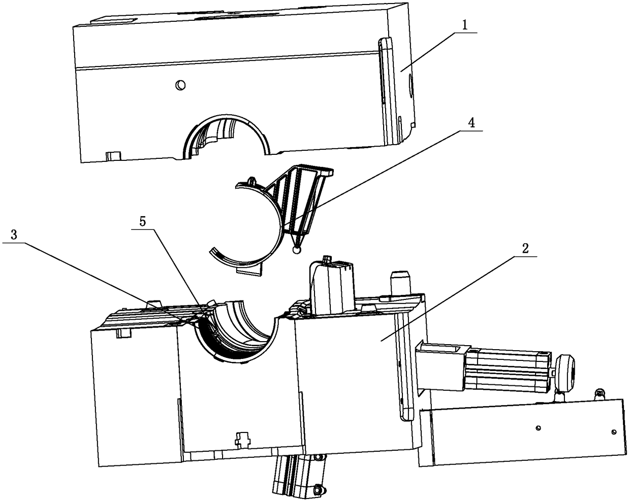
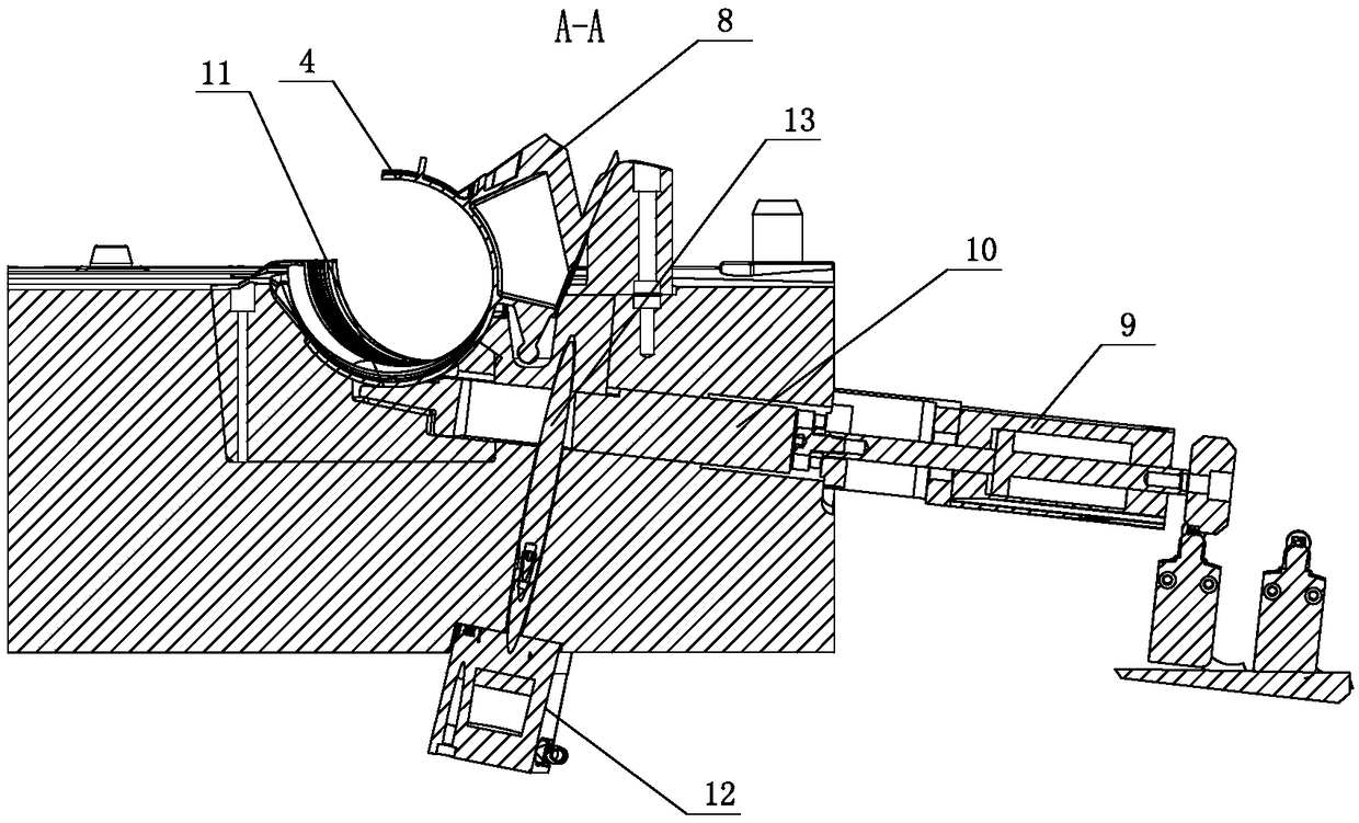
[0027] combine Figure 1~5 , a mold for air filter pipe blow molding, it wraps upper mold 1 and lower mold 2, said upper mold 1 is provided with a first inner concave, lower mold 2 is provided with a second inner concave 3, between upper mold 1 and lower mold When the molds 2 are merged, the first indentation and the second indentation 3 form an empty filter tube cavity, and a connector 4 is embedded in the cavity of the air filter tube, and the first indentation is provided with a first cavity for accommodating the upper part of the connector 4. A groove, the second recess 3 is provided with a second groove 5 for accommodating the lower part of the connector 4, the first groove and the second groove 5 form a space for accommodating the connector 4; the lower mold 2 is provided with A positioning mechanism for positioning the connecting piece 4.

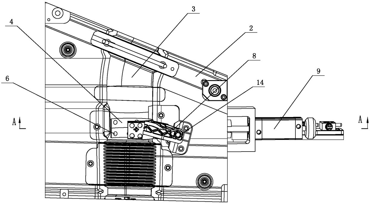
[0028] Connector 4 is provided with at least four connecting holes 6 (eight in this example, also can be four, five, six or ten et...

Embodiment 2

[0037] A mold for air filter pipe blow molding, which includes an upper mold 1 and a lower mold 2, the upper mold 1 is provided with a first concave, the lower mold 2 is provided with a second concave 3, and the upper mold 1 and the lower mold 2 are combined , the first indentation and the second indentation 3 form an air filter tube cavity, and a connector 4 is embedded in the cavity of the air filter tube, and a first groove for accommodating the upper part of the connector 4 is provided on the first indentation , The second concave 3 is provided with a second groove 5 for accommodating the lower part of the connector 4; the lower mold 2 is provided with a positioning mechanism for positioning the connector 4.

[0038] The connecting piece 4 is provided with at least four connecting holes 6 (seven in this example, and can also be four, five, six or ten, etc.), and the connecting holes 6 are distributed at the positions near both ends of the connecting piece 4 .

[0039] The...


PUM


Abstract

The invention discloses a mold for blow molding of an air filter pipe. The mold comprises an upper mold (1) and a lower mold (2), wherein a connecting piece (4) is embedded in a cavity of the air filter pipe, a first groove for accommodating the upper part of the connecting piece (4) is formed in a first inward concave part, and a second groove (5) for accommodating the lower part of the connecting piece (4) is formed in a second inward concave part (3); a positioning mechanism for positioning the connecting piece (4) is arranged on the lower mold (2). An insert of the mold for blow molding ofthe air filter pipe is the connecting piece (4), a vertical positioning block (8) is arranged at the upper part of the connecting piece (4), and a ball positioning piece (15) is arranged at the lowerend of the vertical positioning block (8); a horizontal positioning block (7) is arranged at the lower part of the connecting piece (4); at least four connecting holes (6) are formed in the connecting piece (4) and distributed in the positions near two ends of the connecting piece (4). Compared with the prior art, the production period of the air filter pipe can be shortened, and the preparationcost is lower.

Description

technical field [0001] The invention relates to the technical field of blow molds, in particular to a mold for blow molding an air filter tube and an insert thereof. Background technique [0002] Blow molding mainly refers to hollow blow molding (also known as blow molding), which is a method of blowing a hot-melt parison closed in a mold to form a hollow product by means of gas pressure. It is the third most commonly used plastic processing method, and at the same time It is also a fast-growing plastic molding method. The mold used for blow molding only has a female mold (concave mold). Compared with injection molding, the cost of equipment is lower, the adaptability is stronger, the formability is good (such as low stress), and products with complex undulating curves (shape) can be formed. . [0003] At present, after the air filter tube is blow-molded, the connecting piece is welded at the position reserved on the outer peripheral surface of the air filter tube. Such a ...

Claims


Application Information

Patent Timeline
Patent Type & Authority Applications(China)
IPC IPC(8): B29C49/48B29C49/20B29C33/12
CPCB29C33/12B29C49/20B29C49/48B29C2049/2017B29C2049/2021B29C2049/2086
Inventor 方永杰王锦浪程苗张修恩陆鑫鑫程利波魏一辉陈聪蒋明杰薛乾东葛小翔周华民黄志高刘虹
Owner NINGBO FANGZHENG TOOL
Why Eureka
Try Eureka