Syringe printing positioning mechanism

A positioning mechanism and syringe technology, applied in printing presses, rotary printing presses, printing and other directions, can solve the problems of inability to make individual adjustments, inconsistent product zero lines, etc., to ensure printing accuracy, improve smoothness and non-stickiness, Guarantee the effect of printing accuracy

Active Publication Date: 2020-07-24
浙江环稠机械设备制造有限公司
View PDF1 Cites 0 Cited by
  • Summary
  • Abstract
  • Description
  • Claims
  • Application Information

AI Technical Summary

Problems solved by technology

[0005] The purpose of the present invention is to provide a syringe printing and positioning mechanism, which solves the defect that the existing syringe printing and positioning mechanism uses a whole positioning plate, and when the printing of individual products changes or the printing is unqualified, it cannot be individually adjusted.
[0006] Another object of the present invention is to provide a syringe printing and positioning mechanism, which solves the defect that the printed product zero line of the existing syringe printing and positioning mechanism is not uniform

Method used


Image

  • Syringe printing positioning mechanism
  • Syringe printing positioning mechanism
  • Syringe printing positioning mechanism

Examples


Embodiment 1

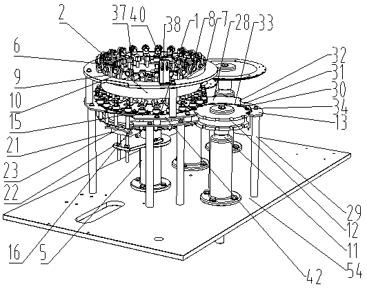
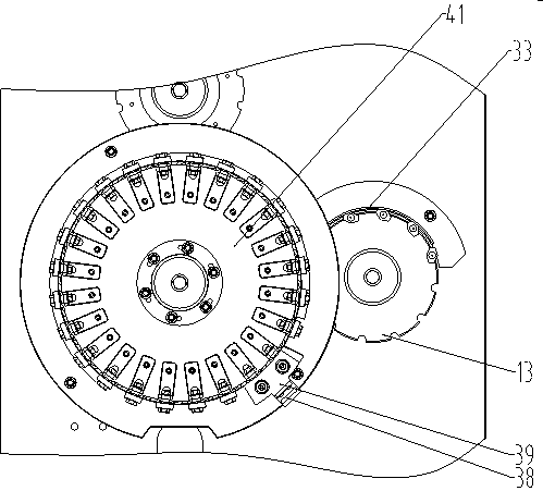
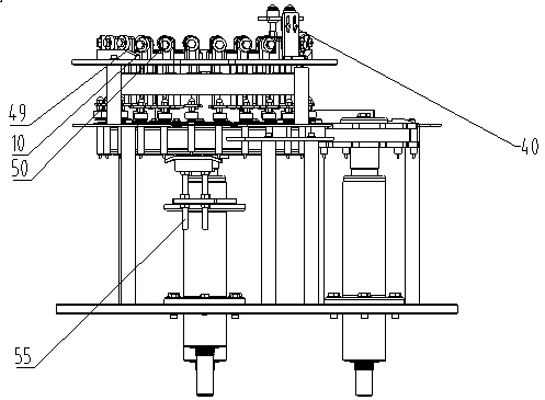
[0035] Such as figure 1 , figure 2 , image 3 , Figure 4 , Figure 5As shown, a syringe printing positioning mechanism provided by the present invention includes: a positioning assembly 1, a pressing and fixing device 2 and a feeding device 3; the pressing and fixing device includes a fixing assembly 4, a printing shaft 5 and a Printing assembly 6, the top of the fixed assembly has an arc-shaped guide plate 7 arranged along the circumferential direction of the printing shaft, and the two ends of the guide plate have slopes 8 inclined from the top of the guide plate to the top plate and bottom plate; the printing assembly includes connecting 9, the top of the connecting piece is equipped with a roller 10, the roller moves along the top surface of the guide plate, and is used to drive the printing assembly to move up and down.

[0036] The feeding device comprises a feed shaft 11 and a feed tray 12 installed on the top of the feed shaft, and a feed fixed disc 13 is install...

Embodiment 2

[0046] A positioning assembly, the positioning assembly includes an upper chuck; a plurality of circumferentially arranged positioning blocks are installed on the upper end surface of the upper chuck, and the positioning blocks are fixed on the upper chuck by detachable positioning fasteners; The side surface of the outer end of the positioning block has an inward depression to form a positioning groove, and the positioning groove is adapted to the outer surface of the handle of the syringe.


PUM


Abstract

The invention provides an injector printing positioning mechanism which comprises a positioning assembly. The positioning assembly comprises an upper chuck and a lower chuck, the edges of the upper chuck and the lower chuck are each provided with a concaved-inwards groove for fixing an injector tube, the upper end face of the upper chuck is provided with multiple positioning blocks arranged in thecircumferential direction, the positioning blocks are fixed to the upper chuck through detachable positioning fasteners, the side faces of the outer ends of the positioning blocks are provided with concaved-inwards positioning grooves, and the positioning grooves are matched with the outer side face of a handle of the injector tube. The multiple independent positioning blocks are adopted to replace a whole positioning disc, and when printing of some products is changed or unqualified, printing can be made qualified by adjusting the separated positioning blocks.

Description

technical field [0001] The invention relates to the field of medical equipment automatic production equipment, in particular to a syringe printing positioning mechanism. Background technique [0002] Medical syringes need to print scale marks on their outer walls to facilitate the use of medical personnel. And the mode of printing scale mark on syringe can be with screen printing, yet screen printing exists speed is slow, needs personnel to operate, adjust in printing process, and the disadvantages such as silk screen is easy to wear and tear. Therefore, people began to use pad printing to print the scale line of the syringe. However, since the printing position of the scale line of the syringe has special requirements, the printing accuracy is high, and no deviation can occur, and the directional printing of the scale line of the syringe cannot be completed by using the existing pad printing machine. Existing syringes use a syringe printing positioning mechanism that ofte...

Claims


Application Information

Patent Timeline
Patent Type & Authority Patents(China)
IPC IPC(8): B41F17/18
CPCB41F17/18B41P2217/10B41P2217/50
Inventor 郑夫青
Owner 浙江环稠机械设备制造有限公司
Why Eureka
Try Eureka