Optical device for repositioning and redistributing an LED's light

a technology of optical devices and leds, applied in semiconductor devices, instruments, lighting and heating apparatus, etc., can solve the problems of led lamps that led lamps are unsuitable for electrically unsuitable, and led lamps are not suitable for direct installation into conventional flashlights

Inactive Publication Date: 2006-04-04
LIGHT ENGINE
View PDF112 Cites 250 Cited by
  • Summary
  • Abstract
  • Description
  • Claims
  • Application Information

AI Technical Summary

Problems solved by technology

Also, the prices of LEDs continue to fall, along with those of the control-electronics to handle variations in battery voltage.
Indeed, LED flashlights are commercially available already, but their optics have to be adapted to the geometry of light-emitting diodes, which only emit into a hemisphere.
Conventional LED lamps are unsuitable for direct installation into conventional flashlights, both electrically and optically.
LED lamps are electrically unsuitable because they are current-driven devices, whereas batteries are voltage sources.
This causes such high currents that the Ohmic heating wi...

Method used


Image

  • Optical device for repositioning and redistributing an LED's light
  • Optical device for repositioning and redistributing an LED's light
  • Optical device for repositioning and redistributing an LED's light

Examples


Embodiment Construction

[0051]The following description of the presently contemplated best mode of practicing the invention is not to be taken in a limiting sense, but is made merely for the purpose of describing the general principles of the invention. The scope of the invention should be determined with reference to the claims.

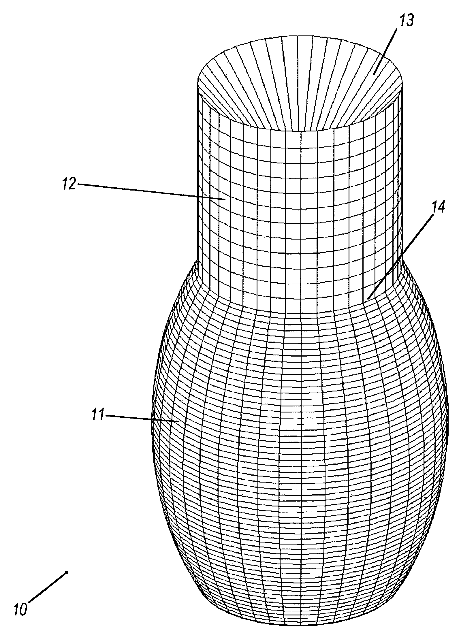
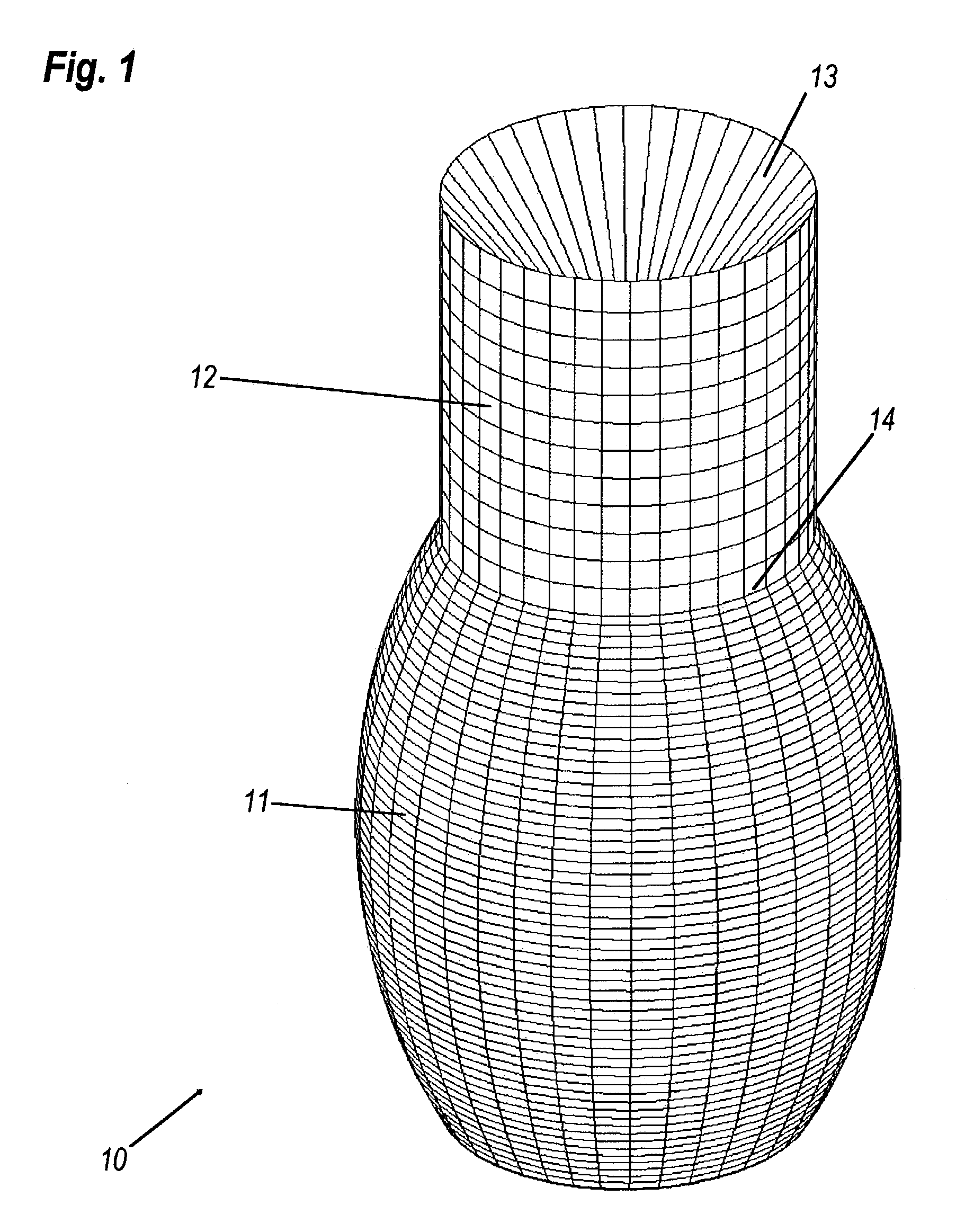
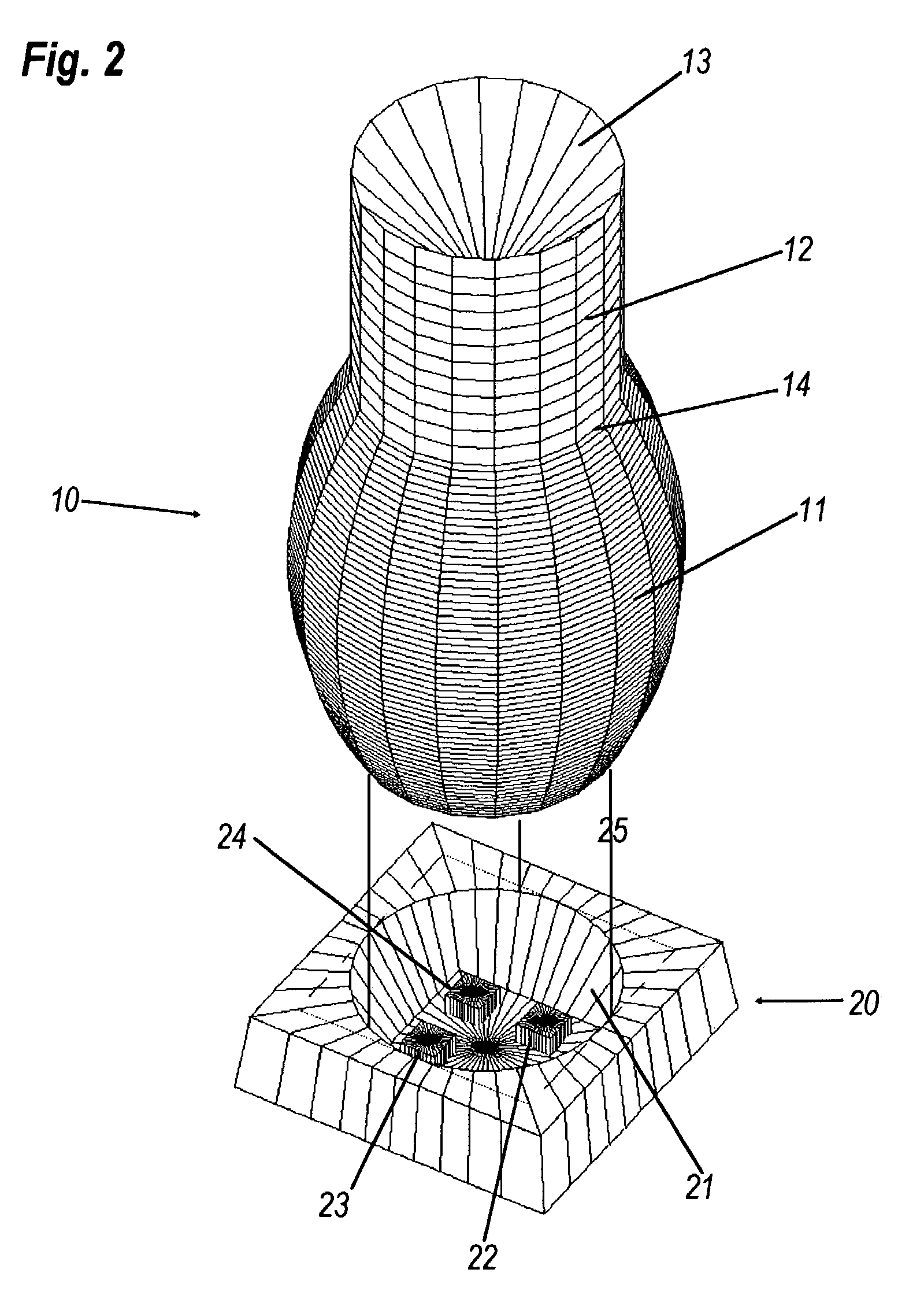
[0052]Referring to FIG. 1, shown is top perspective view of an optical device according to an embodiment of the present invention. Lens 10 comprises lower transfer section 11 and upper ejector section 12.

[0053]The lens 10 is a transparent solid in the general shape of a prolate ellipsoid and is single piece of a transparent material such as acrylic or polycarbonate. It has a rotationally symmetric shape, taller than its diameter. Upper ejector section 12 is cylindrical, with a conical indentation 13 on top of it. Exit plane 14 is the boundary between transfer section 11 and ejector section 12.

[0054]The lower transfer section 11 uses internal reflection to relocate an LED's emission...


PUM


Abstract

An optical device is for spatially displacing the output of a light-emitting diode (LED) and coupling the output to a predominantly spherical emission pattern produced at a useftul height above the LED. The device is made of a transparent dielectric material, such as an injection-molded plastic. It comprises a lower transfer section that receives the LED's light from below and an upper ejector section that receives the transferred light and spreads it spherically. One or more LEDs. are optically coupled to the bottom of the transfer section, which operates by total internal reflection upon their entire hemispherical emission. One embodiment operates as a flashlight-bulb substitute with the ejector section radiating onto a parabolic reflector, which forms the beam. Thus hemisphencally emitting LEDs can be used in parabolic-mirror flashlights wherein these LEDs by themselves may be unsuitable for that role.

Description

[0001]This application claims priority under 35 U.S.C. 119(e) to U.S. Provisional Patent Application No. 60 / 470,691 filed May 13, 2003, of Juan C. Minano et al., for OPTICAL DEVICE FOR LED-BASED LIGHT-BULB SUBSTITUTE, which United States provisional patent application is hereby fully incorporated herein by reference.BACKGROUND OF THE INVENTION[0002]The present invention relates to light-emitting diodes (LEDs), particularly optical means for substituting white LEDs for incandescent and fluorescent light bulbs.[0003]Conventional incandescent lamps of less than 100 lumens output can be matched by the latest white LEDs, albeit at a higher price. At this low end of the lumen range, the majority of incandescent applications are battery-powered. It is desirable to have an LED suitable for direct installation in the place of, for example, a burnt-out flashlight bulb.[0004]LED's can offer superior luminous efficacy over the conventional incandescent lamps used in, for example, battery-operat...

Claims


Application Information

Patent Timeline
IPC IPC(8): G02B6/10F21K99/00F21V5/04F21V7/00G02BH01L29/06H01L33/54
CPCF21K9/52F21V5/04F21V7/0091F21K9/137G02B19/0066G02B19/0071G02B19/0028F21K9/135H01L33/54F21Y2101/02F21K9/232F21K9/233F21K9/61F21Y2115/10
Inventor T
Owner LIGHT ENGINE
Why Eureka
Try Eureka