High strip rate downstream chamber

a downstream chamber and high strip rate technology, applied in the field of wafer processing, can solve the problems of back pressure, slow down the gas flow above the showerhead, and reduce the effect of flow dynamics

Active Publication Date: 2012-10-30
LAM RES CORP
View PDF22 Cites 249 Cited by
  • Summary
  • Abstract
  • Description
  • Claims
  • Application Information

AI Technical Summary

Benefits of technology

[0012]In another embodiment, the apparatus contains an injection means for introducing the gas from the gas source into the cavity through channels while blocking radiation from the gas source from passing through the channels. In various further embodiments, ends of the channels may comprise ejection means for angling gas ejected from the channels into the chamber at angles different from angles of the channels; the upper chamber body may comprise guiding means for guiding the gas in the cavity ejected by the injection means; and / or the injection means may comprise means for absorbing thermal expansion of the injection means, means for eliminating rubbing of mating surfaces of the injection means and at least one of the upper chamber body and gas source, and / or means for adjusting a temperature of the injection means.

Problems solved by technology

A showerhead is similar to a baffle, however, the number and size of holes are such that they create a back pressure.
The creation of these back pressures effectively slows down the gas flow above the showerhead and reduces the effect of flow dynamics.
However, it is complicated to optimize the hole sizes and pattern for the single baffle design.
Baffles used in single baffle designs are also expensive to manufacture due to the various sizes and the large number of holes.
Similarly, while multiple baffle designs may simplify the hole pattern, the use of multiple baffles increases the size and weight of the chamber, as well as increasing the cost of material, if not fabrication.
In showerhead designs, the higher up stream pressure not only lowers the ionization efficiency of the gas source but also increases the radical recombination, and consequently lowers the strip rate.

Method used


Image

  • High strip rate downstream chamber
  • High strip rate downstream chamber
  • High strip rate downstream chamber

Examples


Embodiment Construction

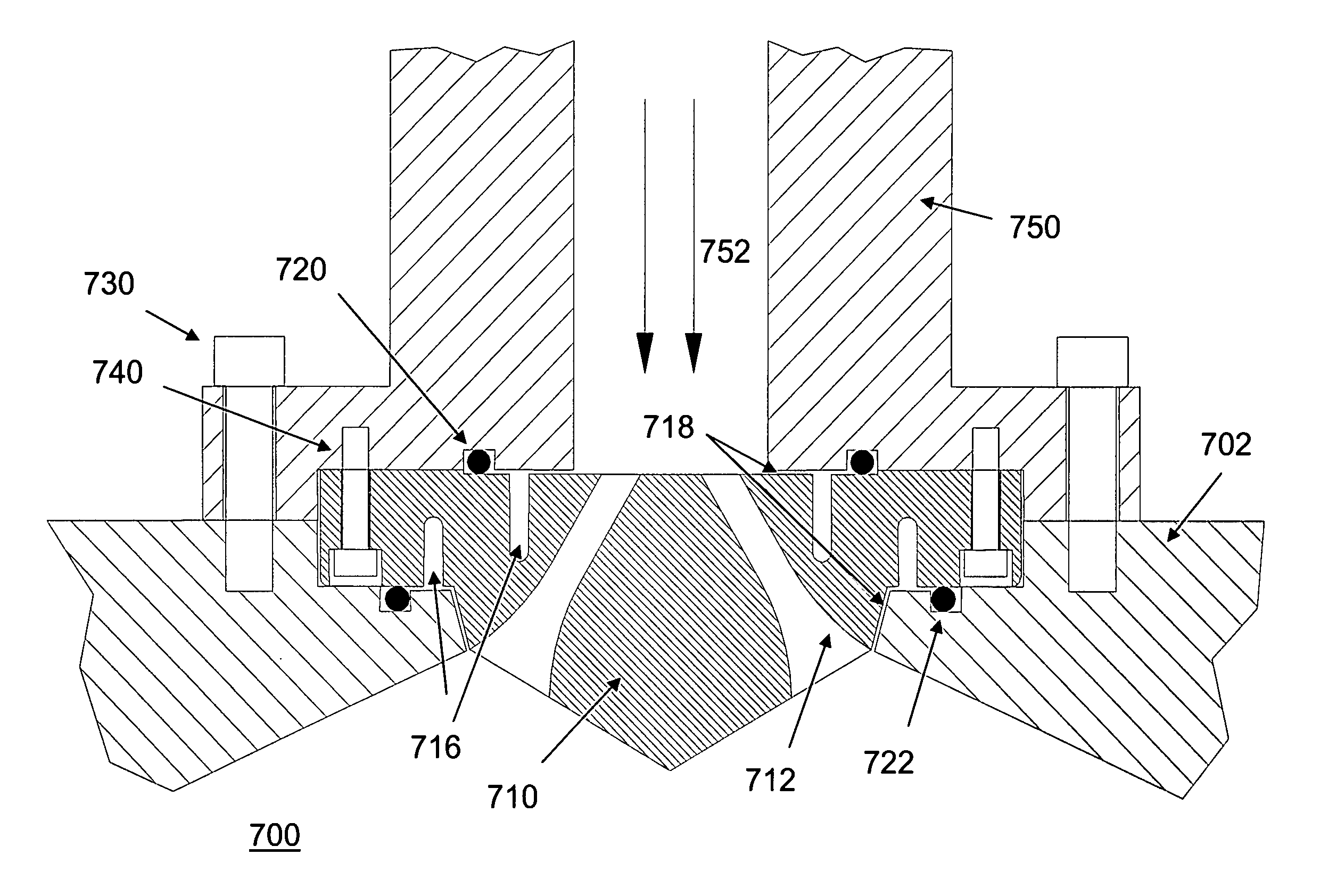
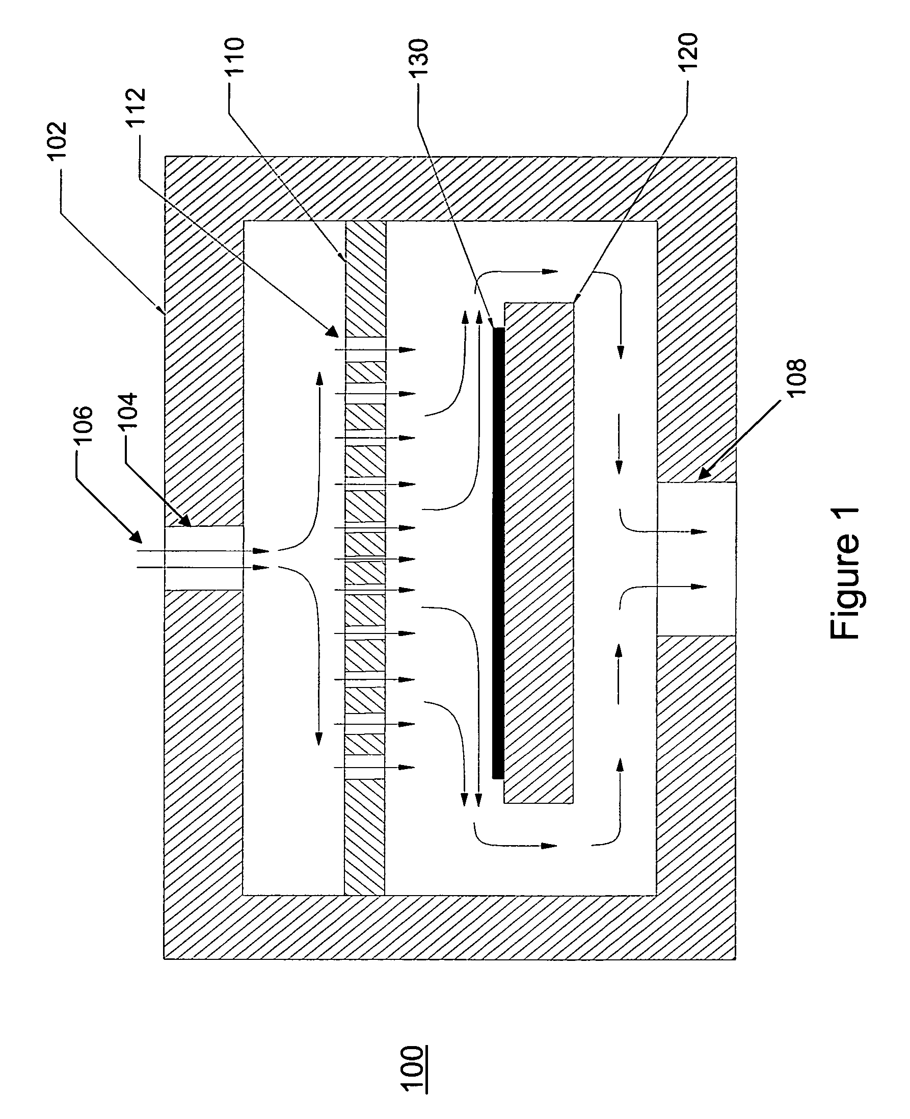
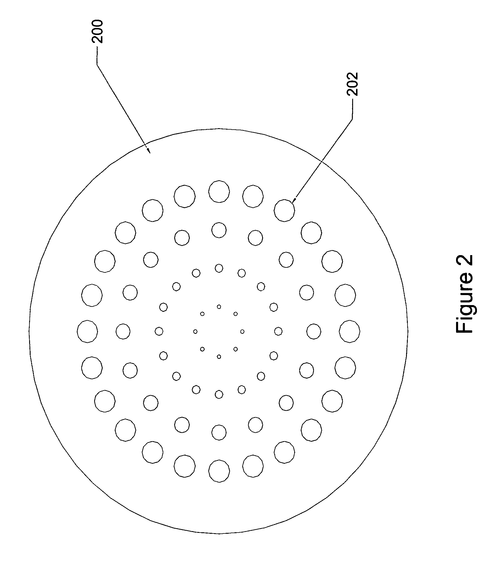
[0029]A gas chamber is described for improving flow of a gas and increasing a strip rate of photoresist on a wafer disposed within the chamber. The gas chamber has a tailored upper chamber body and a gas injector that disperses the gas around the chamber while having a very small surface area to which the gas is exposed. In addition, the gas injector is smaller than known baffles or showerheads, as well as being more economical to manufacture due to its smaller size and relatively simple and short machining process. The term gas, as used herein, includes a gas containing radicals, i.e. a plasma.

[0030]In a stripping process using a gas, typically the gas has a high flow rate and high pressure. As one example, the flow rate of the gas can be 5 standard liters per minute (slm) at 1 Torr. For a gas, the mean free path at this pressure can be obtained with the following equation:

[0031]L=kT2⁢π⁢⁢Pd2

[0032]where L is the mean free path of the gas, k is the Boltzmann constant, T is the absolu...


PUM

PropertyMeasurementUnit
inclination angleaaaaaaaaaa
pressuresaaaaaaaaaa

Abstract

A gas chamber contains upper and lower chamber bodies forming a cavity, a heating chuck for a wafer, a remote gas source, and an exhaust unit. Gas is injected into the cavity through channels in an injector. Each channel has sections that are bent with respect to each other at a sufficient angle to substantially eliminate entering light rays entering the channel from exiting the channel without reflection. The channels have funnel-shaped nozzles at end points proximate to the chuck. The injector also has thermal expansion relief slots and small gaps between the injector and mating surfaces of the chamber and gas source. The temperature of the injector is controlled by a cooling liquid in cooling channels and electrical heaters in receptacles of the injector. The upper chamber body is funnel-shaped and curves downward at an end of the upper chamber body proximate to the chuck.

Description

FIELD OF THE INVENTION[0001]The present application relates to the field of wafer processing. More particularly, the application relates to an etching chamber used in wafer processing.BACKGROUND[0002]Photoresist removal (stripping) is a frequently used process in semiconductor integrated circuit (IC) fabrication. Photoresist is used to define particular patterns on wafers. It is used during lithography, ion implantation and plasma etching (where material other than the photoresist is removed), for example. After these processes, the photoresist is removed from the wafers before continuing to the next process.[0003]Since photoresist stripping is used frequently in semiconductor manufacturing foundries, strippers are designed to have very short process time, i.e. high throughput, to reduce the overall wafer manufacturing cost. While different ways exist to increase a stripper's throughput, they fall into two categories: overhead reduction and strip rate improvement. Overhead includes ...

Claims


Application Information

Patent Timeline
Patent Type & Authority Patents(United States)
IPC IPC(8): C23C16/455C23F1/00C23C16/458H01L21/306C23C16/06C23C16/22
CPCH01J37/32357H01J37/32449H01J37/3244Y10T137/85938Y10T137/0318H01L21/02H01L21/306C03C25/68
Inventor WANG, ING-YANNWINNICZEK, JAROSLAW W.COOPERBERG, DAVID J.EDELBERG, ERIK A.CHEBI, ROBERT P.
Owner LAM RES CORP
Why Eureka
Try Eureka