
Double base close type triangular hoisting device for energy-saving prefabricated member and application method

A lifting device and triangular lifting technology, which is applied in the direction of transportation and packaging, load hanging components, etc., can solve the problems of severe wear at the junction of nylon lifting belts, easy falling of extra-heavy energy-saving prefabricated parts, and violent vibration of energy-saving prefabricated parts. , to achieve the effect of avoiding frequent sliding, improving service life and increasing contact length

Pending Publication Date: 2019-01-08
河南中安征信建筑科技有限公司
View PDF5 Cites 1 Cited by
  • Summary
  • Abstract
  • Description
  • Claims
  • Application Information

AI Technical Summary

Problems solved by technology

[0004] The object of the present invention is to provide an energy-saving prefabricated double-base closed-type triangular lifting device to at least solve the problem of energy-saving prefabrication caused by the energy-saving prefabricated parts not being able to be locked during the current hoisting work. Parts vibrate violently, the joints of nylon lifting belts are severely worn, the service life is low, the lifting is heavy, and extra-heavy energy-saving prefabricated parts are easy to fall, etc.

Method used


Image

  • Double base close type triangular hoisting device for energy-saving prefabricated member and application method
  • Double base close type triangular hoisting device for energy-saving prefabricated member and application method
  • Double base close type triangular hoisting device for energy-saving prefabricated member and application method

Examples


Embodiment 1

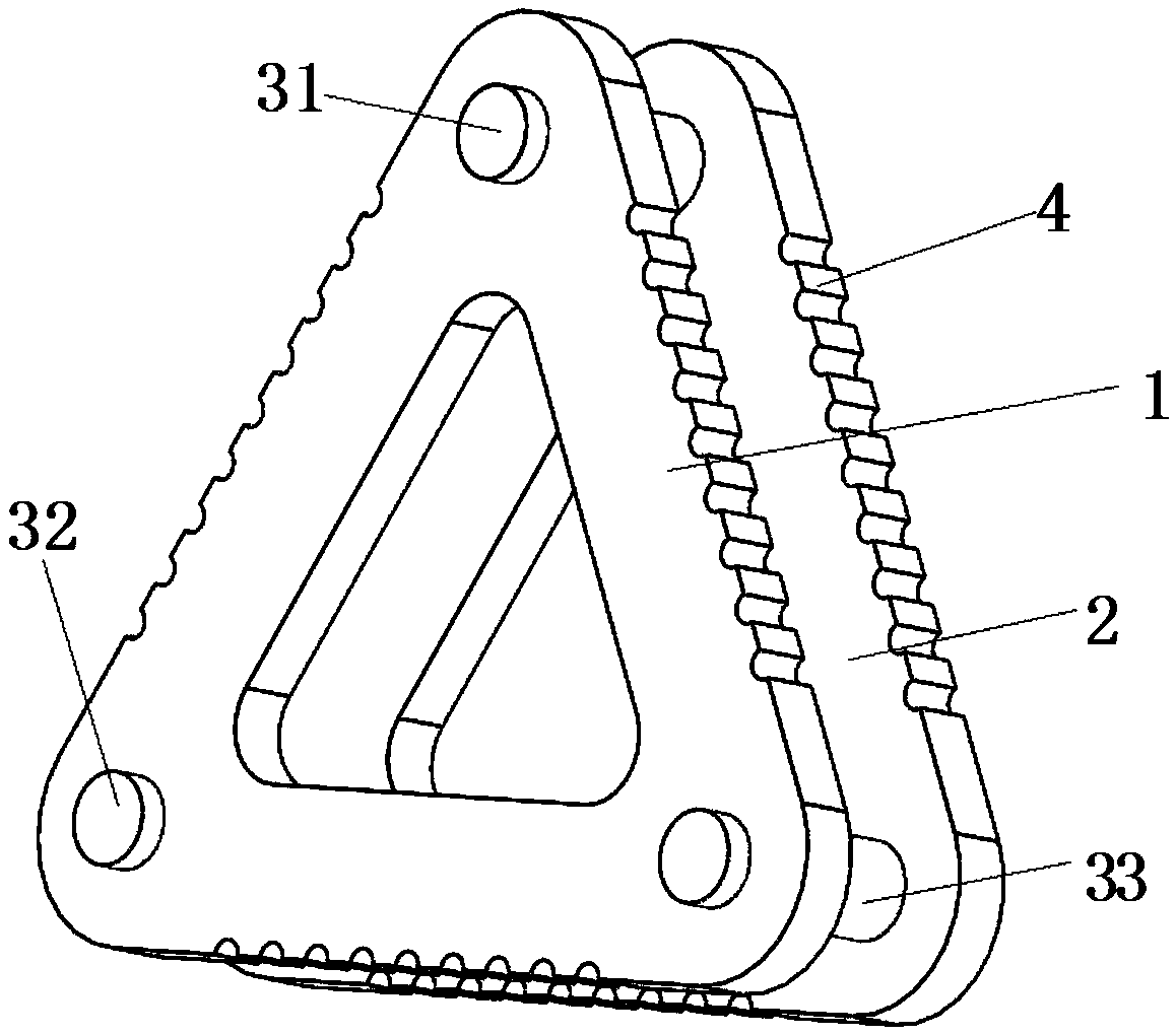
[0050] According to specific embodiments of the present invention, such as Figure 1-Figure 7 Shown is the double-base enclosed triangular lifting device for energy-saving preforms of the present invention, including:

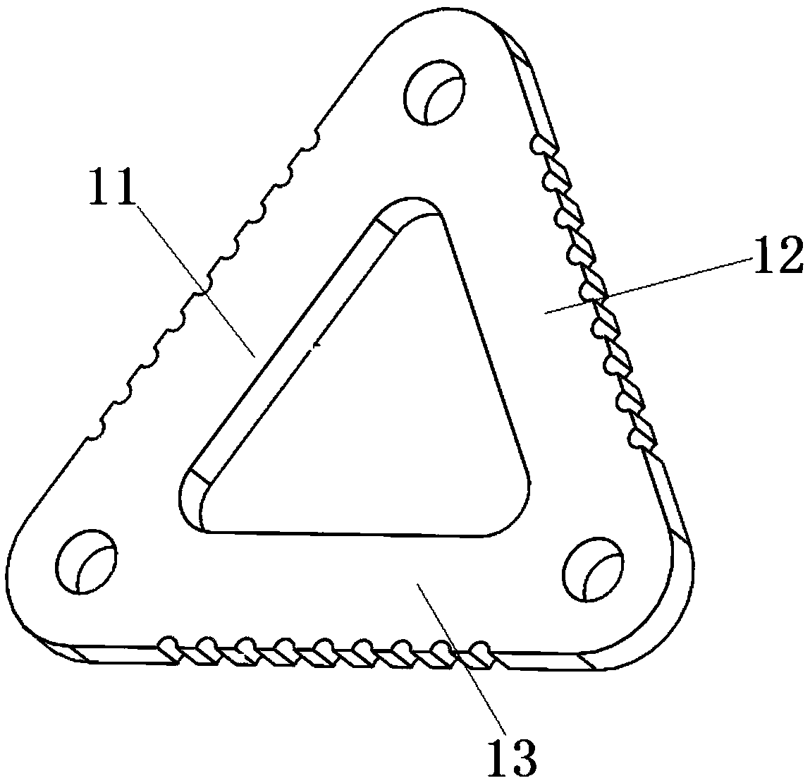
[0051] The hoisting base is cut into triangles from thick steel plates to carry the hoisting shaft. The hoisting base includes hoisting base A1 and hoisting base B2. Hoisting base A1 and hoisting base B2 are exactly the same. Here, hoisting base A1 is taken as an example to describe its structure; Such as figure 2 As shown, the lifting base A1 includes connecting edges, mounting holes, and weight-reducing triangular holes. In order to avoid stress concentration, round chamfers are provided at the corners of the weight-reducing triangular holes and lifting base A1; the connecting edges of the lifting base A1 include the first The connecting side 11, the second connecting side 12 and the bottom connecting side 13, the first connecting side 11 and the second connect...

Embodiment 2

[0066] Such as Figure 8 As shown, in this embodiment, in order to simplify the winding of the sling 8 during the use of the triangular hoisting device and improve efficiency, one of the hoisting shafts is changed to a bolt 5 or a pin shaft. When hoisting, the bolt 5 is removed and the One end of the sling 8 is connected with the lifting device, and the other end bypasses the bottom of the energy-saving preform 9 from the left to the right side of the energy-saving preform 9, and passes the left sling 8 through the open ends of the two lifting bases without lifting shafts Sleeve into the triangular lifting device, place the 8-shaped loop on the head of the sling 8 in the mounting hole between the two lifting bases, pass the bolt 5 or pin through the mounting hole, and then fix one end of the sling 8; After the hoisting operation is completed, the bolt 5 or pin shaft can be removed to easily loosen the sling 8.

[0067] By setting one of the hoisting shafts as a movable bolt 5 or ...

Embodiment 3

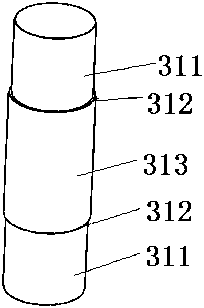
[0070] Such as Picture 9 As shown, in this embodiment, in order to further reduce the wear of the sling 8, a U-groove pulley 7 structure is provided on the outer diameter of the working part 313 of the two fixed lifting shafts of the triangular lifting device. During the lifting process, the lifting The cable 8 is located in the U-shaped groove of the pulley 7, which minimizes the friction between the hoisting shaft and the sling 8 and further reduces the wear of the sling 8; Picture 10 As shown, by adding the pulley 7 structure, the triangle hoisting device can be used as a pulley, greatly expanding the scope of application of the triangle hoisting device. The hoisting shaft of the two pulley 7 structure is matched with the fixed pulley set above to form a pulley block. The heavier energy-saving preform 9 can be lifted with a smaller driving force.

[0071] By setting the V-groove or U-groove pulley 7 structure on the outer diameter of the working part 313 of the hoisting shaft...


PUM


Abstract

The invention provides a double base close type triangular hoisting device for an energy-saving prefabricated member and an application method. The device comprises triangular hoisting bases and hoisting shafts arranged on the hoisting bases. The hoisting shafts separate the adjacent two hoisting bases parallelly. One end of a sling is connected to a hoisting device while the other end of the sling successively bypasses the two hoisting shafts and the energy-saving prefabricated member and are fixed to the other hoisting shaft; one outer sides wall of the hoisting bases lean against the outerside wall of the energy-saving prefabricated member, so that the energy-saving prefabricated member is hoisted. The device can fill a triangular cavity formed by the upper side of the energy-saving prefabricated member and the sling effectively, so that the hoisting stability is ensured, and the service life of the sling is prolonged; anti-skid grooves are formed in three connecting edges. In thehoisting operation, the anti-skid grooves press the energy-saving prefabricated member, so that the friction force is improved, the energy-saving prefabricated member is prevented from sliding and falling off, and the safety of the hoisting operation is improved greatly. A retainer ring is arranged at the outer end of the hoisting shaft. The device has important meaning in a hoisting operation ofthe energy-saving prefabricated member.

Description

Technical field [0001] The invention belongs to the field of equipment hoisting, and in particular relates to a double-base enclosed triangular hoisting device for energy-saving preforms and a use method. Background technique [0002] When hoisting short bundles or single rod-shaped materials with a single hook, the existing slings usually use a single wire rope with a "8" head or a nylon hoisting belt with a "8" head for hoisting. In the process, one end of the hoisting strap is sleeved into the rope sleeve at the other end to form a rope loop. The rope loop fixes the middle of the bar for hoisting operations; when hoisting a long bar, two hoisting straps are used. A hoisting belt fixes the two ends of the bar for hoisting. In the actual hoisting process, the steel wire rope or nylon hoisting belt will form a triangular cavity area directly above the bar during the process of locking the bar. If the cavity is too large, the bar will not be locked, and the bar will slip off, ca...

Claims


Application Information

Patent Timeline
IPC IPC(8): B66C1/18
CPCB66C1/18Y02B50/00
Inventor 杨小明董明利赵元楷芦冬来付林林段志华
Owner 河南中安征信建筑科技有限公司
Learn More