
Road roller for adjusting heights of steel wheels on basis of detected road surfaces

A technology of road rollers and steel wheels, applied in the field of road rollers, can solve the problems of poor road compaction quality, damaged rolling equipment, low rolling efficiency, etc., and achieve the effects of reducing pressure, speeding up driving, and improving rolling quality.

Inactive Publication Date: 2019-01-08
南安市劲沣电子科技有限公司
View PDF9 Cites 2 Cited by
  • Summary
  • Abstract
  • Description
  • Claims
  • Application Information

AI Technical Summary

Problems solved by technology

[0004] The main purpose of the present invention is to overcome the deficiencies of the prior art, to provide a road roller that adjusts the height of the steel wheel based on the detection of the road surface, so as to solve the uneven dirt road that generally piles up soil and has large depressions when the same road surface is rolled, as proved by construction practice. The speed of rolling should not be too fast, otherwise not only the rolling efficiency will be low and the quality of road compaction will be poor, but also the rolling equipment may be damaged; if the rolling speed is slow, the road surface needs to be rolled many times. The problem of large number and low work efficiency

Method used


Image

  • Road roller for adjusting heights of steel wheels on basis of detected road surfaces
  • Road roller for adjusting heights of steel wheels on basis of detected road surfaces
  • Road roller for adjusting heights of steel wheels on basis of detected road surfaces

Examples


Embodiment Construction

[0024] The following will clearly and completely describe the technical solutions in the embodiments of the present invention with reference to the accompanying drawings in the embodiments of the present invention. Obviously, the described embodiments are only some, not all, embodiments of the present invention. Based on the embodiments of the present invention, all other embodiments obtained by persons of ordinary skill in the art without making creative efforts belong to the protection scope of the present invention.

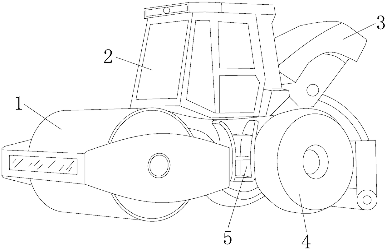
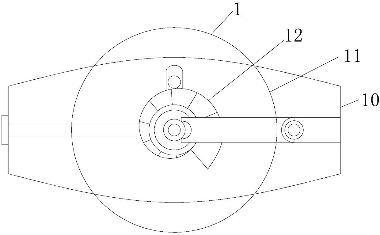
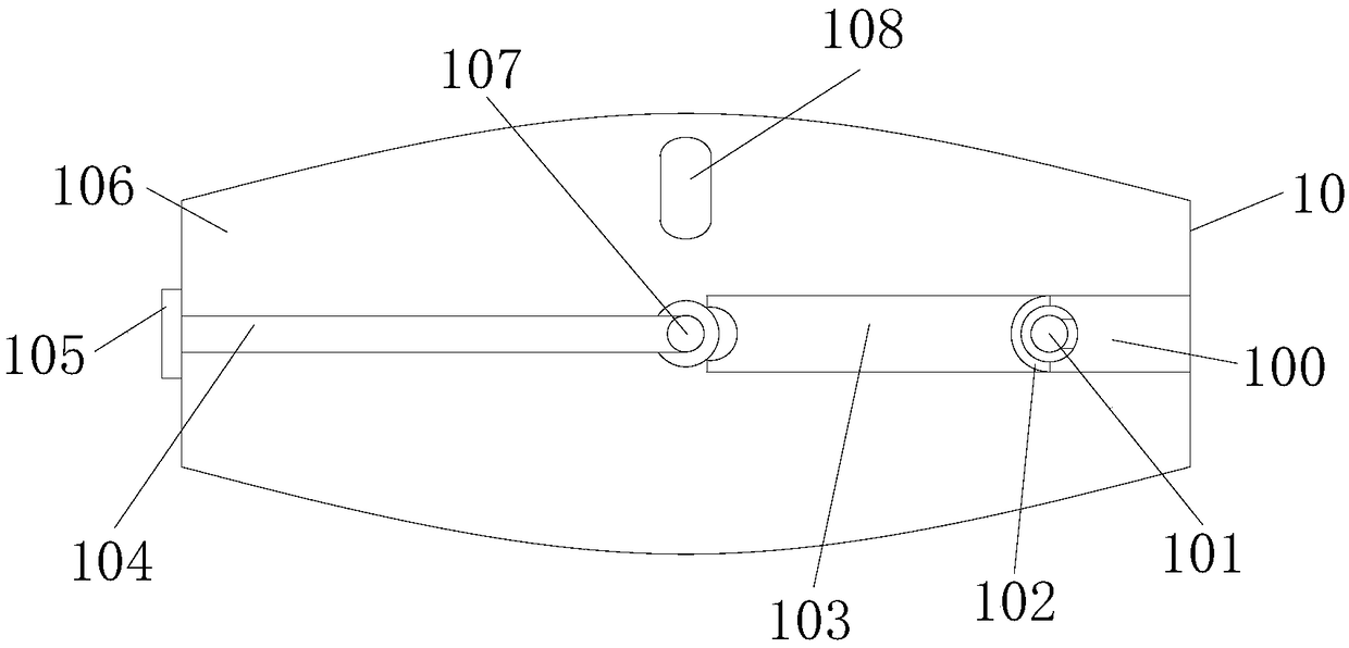
[0025] see Figure 1-9, the present invention provides a technical scheme for adjusting the height of the steel wheel based on detecting the road surface: its structure includes a steel wheel structure 1, a control room 2, a rear cover 3, a rear wheel structure 4, and a machine base 5. The control room 2 and the machine The base 5 is locked, the rear cover 3 is connected to the machine base 5, the steel wheel structure 1 and the rear wheel structure 4 are inst...


PUM


Abstract

The invention discloses a road roller for adjusting heights of steel wheels on basis of detected road surfaces. The road roller structurally comprises a steel wheel structure, a control room, a rear cover, a rear wheel structure and an engine base, wherein the control room is locked with the engine base; the rear cover is in shaft connection with the engine base; the steel wheel structure and therear wheel structure are mounted on the engine base; the steel wheel structure consists of a surrounding frame structure, a steel wheel structure and a rotation screw mechanism, which are located at asame axis; the steel wheel structure is in shaft connection with the surrounding frame structure; and the rotations screw structure is in shaft connection with the surrounding frame structure. The road roller is capable of realizing efficient grinding through reducing the height of the steel wheel structure for higher unsurfaced roads with more pile solids and raising or keeping the height of thesteel wheel structure for the sunken unsurfaced roads with less pile solids, improving the running speed to ensure the compaction quality and efficiency and decreasing the grinding times; and meanwhile, auxiliary wheels are added on the tires to reduce the pressure applied on the ground by the rear wheels, so that the grinding quality is further improved.

Description

technical field [0001] The invention relates to the field of road construction, in particular to a road roller for adjusting the height of steel wheels based on road surface detection. Background technique [0002] Road roller, also known as soil compactor, belongs to the category of road equipment in construction machinery. It is a road repair equipment based on detecting the road surface and adjusting the height of the steel wheel. It uses the gravity of the machine itself to crush sandy, semi-cohesive and cohesive soils. , roadbed stabilized soil and asphalt concrete pavement layer; the rolling speed of the road roller has a direct impact on the compaction quality and production efficiency. [0003] The construction practice of the prior art has proved that when rolling on the same road surface, the uneven soil road with large piles of soil and large depressions should not be rolled too fast, otherwise not only the rolling efficiency is low and the road compaction quality...

Claims


Application Information

Patent Timeline
IPC IPC(8): E01C19/28
CPCE01C19/282E01C19/288
Inventor 戴宝木
Owner 南安市劲沣电子科技有限公司
Learn More