Optical fiber parameter measuring system and method

A technology of optical fiber parameter and measurement system, applied in the field of optical fiber, can solve the problems of low practicability, single function, complex structure, etc.

Pending Publication Date: 2019-01-08
WUHAN UNIV OF TECH
View PDF0 Cites 4 Cited by
  • Summary
  • Abstract
  • Description
  • Claims
  • Application Information

AI Technical Summary

Problems solved by technology

[0003] In actual use, many institutions are developing beam analysis systems, but existing products generally have problems such as single function, low practic

Method used


Image

  • Optical fiber parameter measuring system and method
  • Optical fiber parameter measuring system and method
  • Optical fiber parameter measuring system and method

Examples


Embodiment Construction

[0032] In order to better understand the above-mentioned technical solution, the above-mentioned technical solution will be described in detail below in conjunction with the accompanying drawings and specific implementation methods.

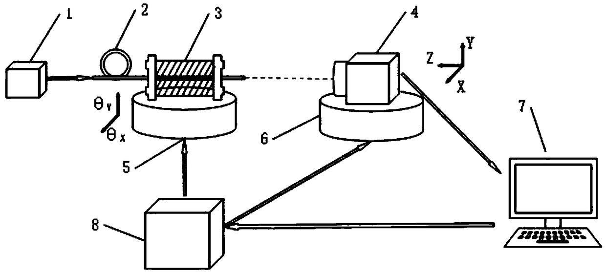
[0033] This embodiment provides a fiber optic parameter measurement system, such as figure 1 As shown, it includes a laser light source 1 , an optical fiber fixture 3 , a camera 4 , a two-dimensional electric angle stage 5 , a three-dimensional electric translation stage 6 , a host computer 7 , and an optical fiber alignment controller 8 .

[0034] Wherein, the laser light source 1 is used to generate laser light, and the adopted response wavelength is 400nm-1100nm.

[0035] The optical fiber clamp 3 is used to fix the optical fiber 2 to be tested. Specifically, the optical fiber clamp 3 is provided with a groove that can place the optical fiber 2 to be tested. After the optical fiber clamp 3 is opened, the optical fiber to be tested can be place...


PUM


Abstract

The invention belongs to the technical field of optical fibers, and discloses an optical fiber parameter measuring system and method. A to-be-measured optical fiber is fixed in an optical fiber clamp,the optical fiber clamp is fixed on a two-dimensional motorized goniometers stage, and a camera is fixed on a three-dimensional electric translation stage; laser is generated by adopting a laser light source, after passing through the to-be-measured optical fiber, the laser is irradiated on an area array sensor of the camera to form a light spot, and the camera transmits light spot image information collected in real time to an upper computer; an optical fiber collimation controller and the upper computer cooperatively control the movement of the two-dimensional electric motorized goniometersstage and the three-dimensional electric translation stage, so that an emergent light beam of the to-be-measured optical fiber and the area array sensor of the camera are perpendicular to each other;and the upper computer performs calculation according to the collimated light spot image information to obtain optical fiber parameters. According to the system and the method, the parameters of themonomode optical fiber can be measured.

Description

technical field [0001] The invention relates to the field of optical fiber technology, in particular to a system and method for measuring optical fiber parameters. Background technique [0002] Optical fiber not only promotes the development of communication and informatization, but also has a wide range of applications in science, industry and medicine. Due to its advantages in long-distance transmission, single-mode fiber has more and more application scenarios. For example, in medical applications, the lighting system used in advanced surgical microscopes is designed by taking advantage of some characteristics of optical fibers. When performing ENT or narrow abdominal surgery, ordinary lighting cannot meet the surgical lighting requirements. Generally, the lighting methods used are coaxial lighting and oblique lighting. The angle of oblique lighting is calculated according to the divergence angle and off-axis degree of the optical fiber. The special light source is real...

Claims


Application Information

Patent Timeline
IPC IPC(8): G01M11/00
CPCG01M11/00
Inventor 吴友宇黄榕秦战强赵光雄梁小宇刘江慧
Owner WUHAN UNIV OF TECH
Why Eureka
Try Eureka