
Circuit structure for reducing low dropout (LDO) power supply static current and control method of circuit structure

A technology of quiescent current and line structure, which is applied in the direction of control/regulation system, adjustment of electrical variables, instruments, etc., can solve the difficult problems of increasing the magnification of the horizontal PNP tube, increasing the power consumption of the device, reducing the power efficiency of the device, etc., to achieve the reduction Power supply quiescent current, the effect of improving output power efficiency

Active Publication Date: 2019-01-08
XIAN MICROELECTRONICS TECH INST
View PDF9 Cites 0 Cited by
  • Summary
  • Abstract
  • Description
  • Claims
  • Application Information

AI Technical Summary

Problems solved by technology

Even by sacrificing the withstand voltage (increasing the implantation concentration of the p+ region in the process and strengthening the control of the width of the PNP base region in the layout design), it is difficult to greatly improve the magnification of the lateral PNP tube
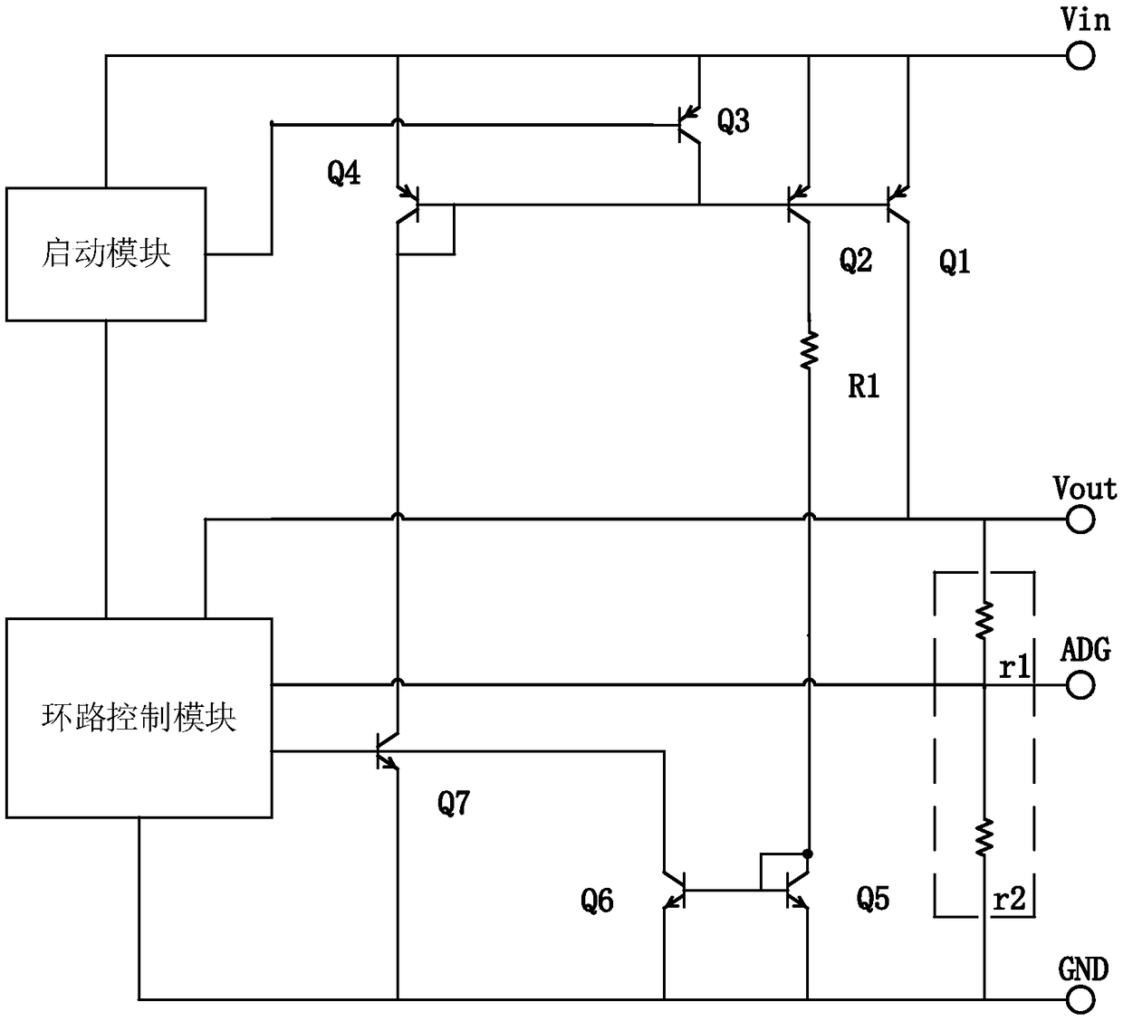
Therefore, the base injection current of the power tube (using lateral PNP) cannot be ignored. Due to the low amplification factor of the lateral PNP tube, the quiescent current of the device is large, especially when the device is working under heavy load conditions, most of the quiescent current of the power supply comes from the power tube. The base injection current increases the power consumption of the device itself and greatly reduces the power efficiency of the device output

Method used


Image

  • Circuit structure for reducing low dropout (LDO) power supply static current and control method of circuit structure
  • Circuit structure for reducing low dropout (LDO) power supply static current and control method of circuit structure
  • Circuit structure for reducing low dropout (LDO) power supply static current and control method of circuit structure

Examples


Embodiment Construction

[0027] The present invention will be further described in detail below in conjunction with specific embodiments, which are explanations of the present invention rather than limitations.

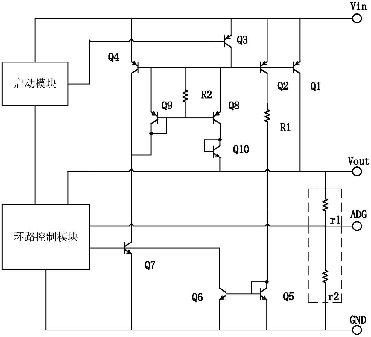
[0028] The present invention adopts the horizontal PNP as the circuit structure for reducing the quiescent current of the LDO power supply, including a start-up module, a loop control module, a power output circuit for reducing the quiescent current of the power supply, and a current-limiting control circuit. Among them, the power output line for reducing the quiescent current of the power supply is composed of PNP bipolar transistors Q1, Q3, Q4, Q8, Q9, R2 and NPN bipolar transistors Q7, Q10, and the current limiting control circuit is composed of resistor R1, PNP bipolar transistors Pole transistor Q2 and NPN type bipolar transistors Q5 and Q6, the loop control block module includes a bandgap reference, an error amplifier and other circuit structures in addition to the loop control circuit. ...


PUM


Abstract

The invention relates to a circuit structure for reducing a low dropout (LDO) power supply static current and a control method of the circuit structure. A relatively small power supply static currentcan be enabled to be obtained during working under a heavy load condition of a device, the power consumption is reduced, and the power efficiency during application is improved. The circuit structurecomprises a starting module, a loop control module, a power output circuit and a current-limiting control circuit, wherein the power output circuit is used for reducing the power supply static current. A power output circuit structure takes a transverse PNP as a power output tube to reduce the power supply static current, when the device works in the heavy load condition, an injection current introduced due to low Q1 amplification rate can be basically neglected, the power supply static current is greatly reduced, and the output power efficiency of the device is improved; and the defect of lowamplification rate of a transverse PNP tube fabricated on the basis of domestic radiation-resistant dual-pole process to cause a relatively large power supply static current under a heavy load outputis overcome, and the situation that a Vout end voltage is higher than a power supply Vin during application of the device Q10 is prevented.

Description

technical field [0001] The invention relates to the technical field of integrated circuit design, in particular to a circuit structure and a control method for reducing the quiescent current of an LDO power supply. Background technique [0002] The power transistor is an essential component module in the chip of the dual high-power LDO device. Using the lateral PNP transistor as the output power transistor can reduce the input and output voltage (Low Dropout voltage) of the device to below 600mV, or even lower. [0003] In the prior art, such as figure 1 As shown, it is a line structure of a certain type of circuit in foreign countries that uses a horizontal PNP tube as the output power tube. The circuit is mainly composed of a starting module, a loop control module, a power output circuit and a current limiting control circuit. Among them, the power output circuit is composed of PNP bipolar transistor Q1 (power output tube), Q3, Q4 and NPN bipolar transistor Q7, and the c...

Claims


Application Information

Patent Timeline
Patent Type & Authority Applications(China)
IPC IPC(8): G05F1/56
CPCG05F1/56
Inventor 廖雪魏海龙
Owner XIAN MICROELECTRONICS TECH INST
Learn More