Articulated intelligent CT scanning table

A CT scanning and articulation technology, applied in the field of CT scanning bed, can solve the problems that the medical personnel cannot automatically control the rotation range of the inspected person, the X-rays of the angiography machine cannot see through, and the bed body rotation cannot be realized. Achieve the effect of good rigidity, smoothness and high precision

Pending Publication Date: 2019-01-11
柳州友助科技有限公司
View PDF0 Cites 1 Cited by
  • Summary
  • Abstract
  • Description
  • Claims
  • Application Information

AI Technical Summary

Problems solved by technology

[0002] Existing CT scanning beds can only realize vertical and horizontal movement in the form of Cartesian coordinates, but cannot realize bed rotation. When the human body is lying on the CT scanning bed for X-ray irradiation, when the human body needs to turn sideways at a small angle, the medical staff It can only ask the person under inspection to turn his body, and the medical staff cannot automatically control the degree of rotation of the person under inspection, and the purpose of fast and accurate inspection cannot be achieved.
In addition, under the bed body of the existing CT scanning bed, metal guide rails or crawlers are used as guides to realize horizontal movement. The X-rays of angiography machines cannot see through the metal guide rails, and cannot complete a full range of perspective imaging diagnosis.

Method used


Image

  • Articulated intelligent CT scanning table
  • Articulated intelligent CT scanning table
  • Articulated intelligent CT scanning table

Examples


Embodiment Construction

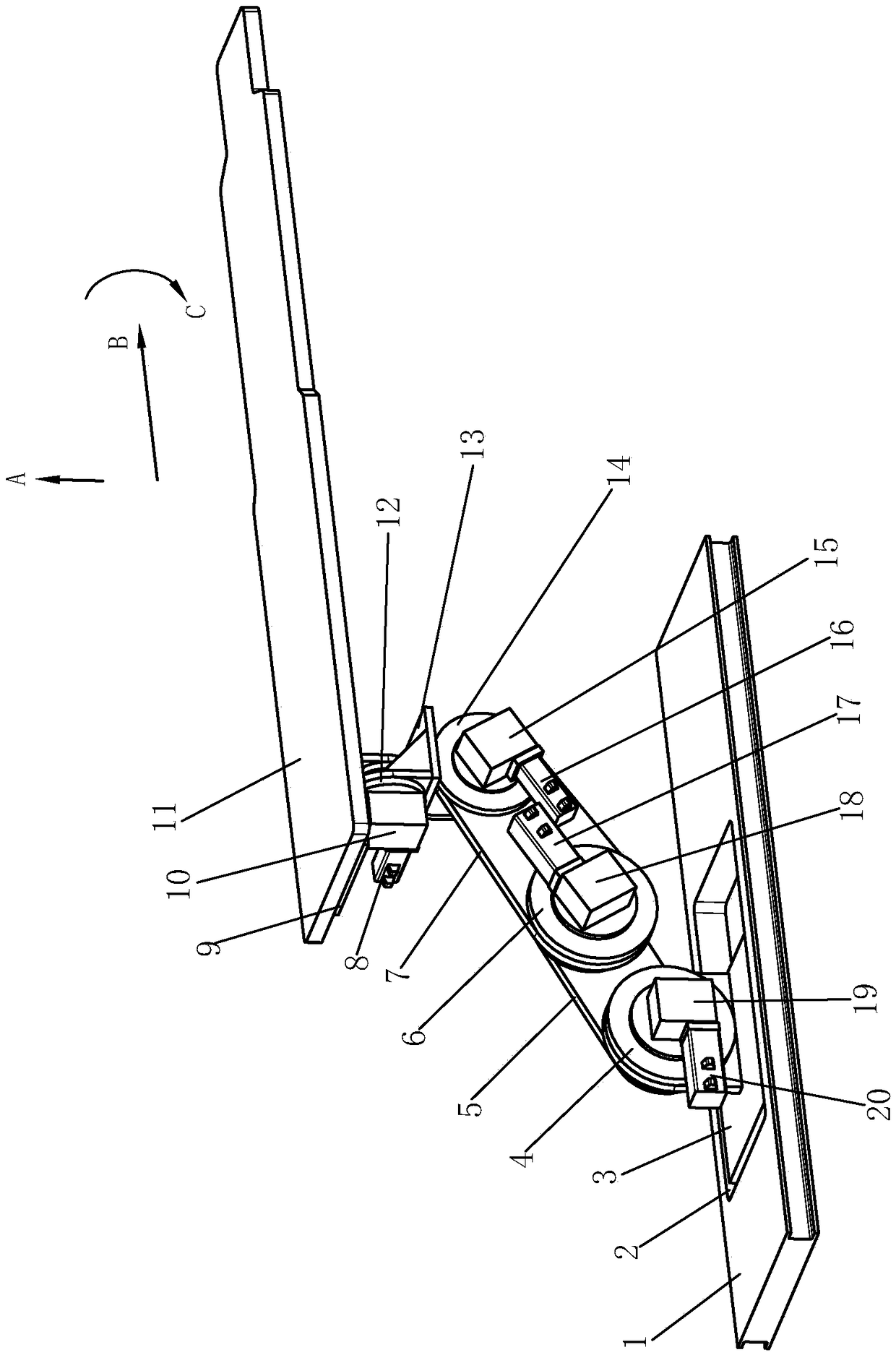
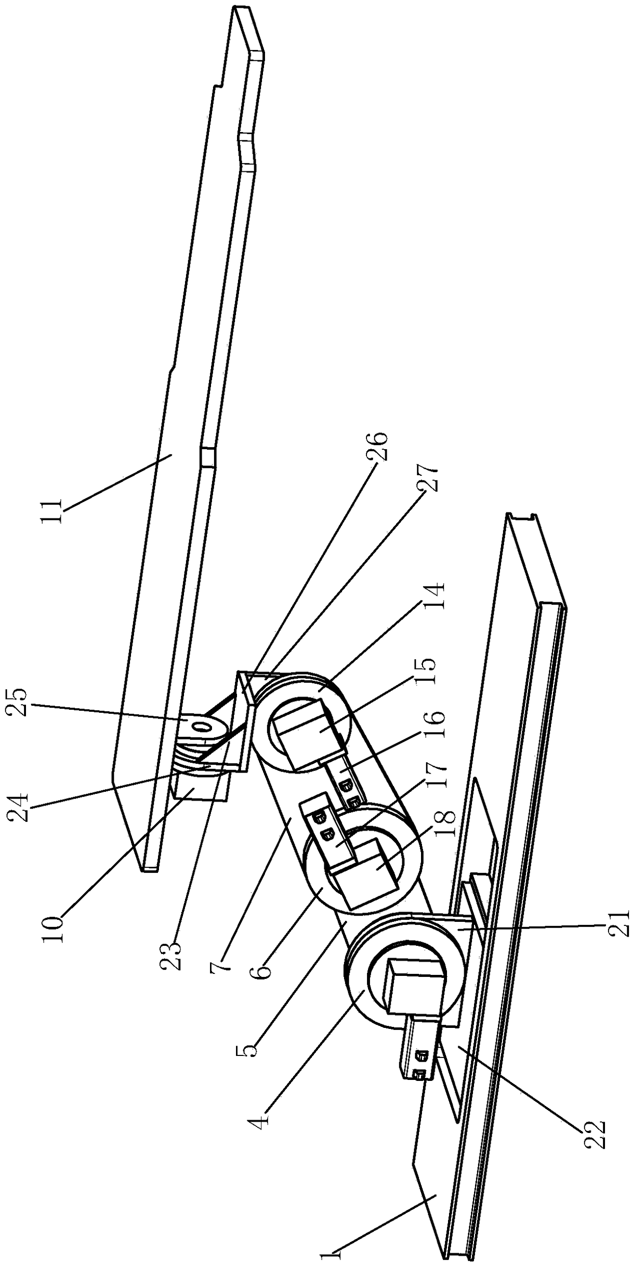
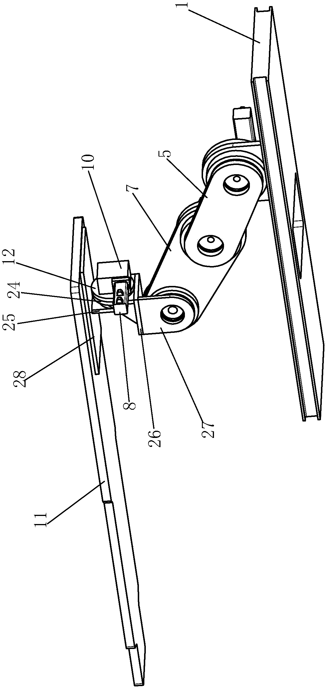
[0018] Such as Figure 1 to Figure 3 As shown, the articulated intelligent CT scanning bed of the present invention includes a base frame 1, a first axis base 3, a first axis articulated arm 5, a second axis articulated arm 7, a third axis connecting seat 13, a bed board connecting seat 9, and Metal bed plate 11, servo motor, worm gear reducer, RV reducer.

[0019] The servo motors include servo motor Ⅰ20, servo motor Ⅱ17, servo motor Ⅲ16, and servo motor Ⅳ8. Worm gear reducer includes worm gear reducer Ⅰ19, worm gear reducer Ⅱ18, worm gear reducer Ⅲ15, worm gear reducer Ⅳ10. RV reducer includes RV reducer I4, RV reducer II6, RV reducer III14, RV reducer IV12.

[0020] The first shaft base 3 includes a base horizontal connecting plate 22 and a base vertical connecting plate 21. The base vertical connecting plate 21 is connected to the base horizontal connecting plate 22, and the base horizontal connecting plate 22 is positioned on the base frame 1. The bottom frame 1 is provided...


PUM


Abstract

The invention relates to an articulated intelligent CT scanning table, including a base frame, a first axle base, a first axle articulated arm, a second axle articulated arm, a third axle connector, abedboard connecting seat, a non-metallic bedplate, four servo motors, four worm and gear reducers, four RV reducers, wherein the first axle base is positioned on the base frame; a fixing end of the RV reducer I is connected with the upper end of the first axle base, the output end of the RV reducer I is connected with the lower end of the first axle articulated arm; a fixing end of the RV reducerII is connected with the lower end of the second axle joint arm; the output end of the RV reducer II is connected with the upper end of the first axle articulated arm; a fixing end of the RV reducerIII is connected with the upper end of the second axle joint arm; the output end of the RV reducer III is connected with the lower end of the third axle connecting seat; the fixed end of the RV reducer IV is connected with the upper end of the third axle connecting seat; the output end of the RV reducer IV is connected with the bed plate connecting seat; the servo motors are respectively connectedwith the corresponding worm gear reducer; and the worm gear reducer is respectively connected with the corresponding RV reducer.

Description

Technical field [0001] The invention relates to the technical field of medical supplies, in particular to a CT scanning bed. Background technique [0002] Existing CT scanning beds can only achieve vertical and horizontal movement in rectangular coordinates, and cannot achieve bed rotation. When the human body is lying on the CT scanning bed to irradiate X-rays, when the human body needs to be sideways at a small angle, medical staff The person under inspection can only be asked to rotate the body, and the extent of the person under inspection cannot be automatically controlled by the medical staff, and the purpose of rapid and accurate inspection cannot be achieved. In addition, the underside of the bed body of the existing CT scanning bed is guided by metal rails or crawlers to achieve horizontal movement. X-rays of the angiography machine cannot see through the metal rails and cannot complete a full range of perspective imaging diagnosis. Summary of the invention [0003] The ...

Claims


Application Information

Patent Timeline
Patent Type & Authority Applications(China)
IPC IPC(8): A61B6/04A61B6/03
CPCA61B6/0407A61B6/032A61B6/504
Inventor 周锦忠陈政
Owner 柳州友助科技有限公司
Why Eureka
Try Eureka