Biochip and chip control method

A biochip and control method technology, applied in chemical instruments and methods, laboratory utensils, laboratory containers, etc., can solve the problem of large consumption of reagents, multiple liquid paths and waste liquid discharge, and inability to achieve large-scale automated analytical instruments. Accuracy and other issues, to achieve the effect of simple and convenient operation

Pending Publication Date: 2019-01-11
HUNAN LEGEND AI CHIP BIOTECH CO LTD
View PDF1 Cites 7 Cited by
  • Summary
  • Abstract
  • Description
  • Claims
  • Application Information

AI Technical Summary

Problems solved by technology

[0012] 1. Complex structure and inconvenient maintenance
[0013] 2. There are many liquid paths and waste liquid discharge
[0014] 3. The sample needle needs to be cleaned and other operations, which consume a large amount of reagents
[0015] 4. Portable and on-site instant diagnosis cannot be achieved
[0018] However, because this serial microfluidic chip technology is based on the above-mentioned inherent characteristics, it cannot achieve the precision of large-scale automated analytical instruments, and has the following disadvantages:
[0019] 1. This method cannot avoid cross-contamination
[0020] 2. This method cannot achieve accurate sample addition of reagent volume
[0021] 3. The mixing process is irreversible, and there is a risk of inconsistent mixing degree
[0022] 4. The cleaning process is irreversible, and there is a risk of incomplete cleaning
However, this patent uses ice as the spool, so it cannot be used for storage of reagents, and there is no spool under normal conditions; further, ice is easy to react with reagents, and ice is too large as a spool (it cannot be used as a valve core). to the micron level), precise control cannot be achieved. In addition, if the patent is used on a microfluidic chip, then the chip needs to be implanted with circuits, which will further increase the difficulty of chip manufacturing and reduce its reliability.

Method used


Image

  • Biochip and chip control method
  • Biochip and chip control method
  • Biochip and chip control method

Examples


Embodiment Construction

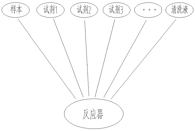
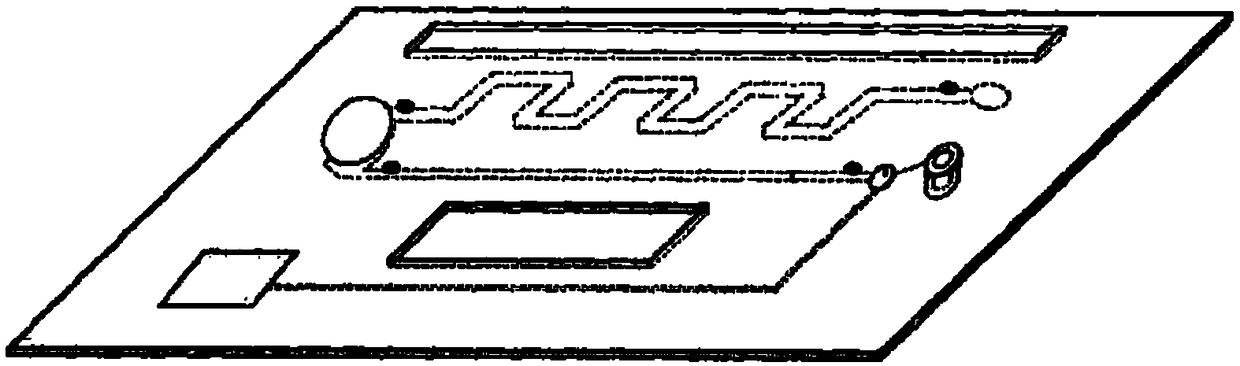
[0121] A biochip, such as Figure 5 , shown in 11,12, it comprises chip substrate 12, is arranged on the quantitative sampling device 20 on the chip substrate 12, a plurality of reagent chambers 16 and reactor 10; Each described reagent chamber 16 is provided with described reactor 10 communicated with the pipelines 17, each pipeline 17 is provided with a normally closed micro-valve 18; the quantitative sampling device has a sample outlet 402, and the sample outlet 402 is communicated with the reactor 10. The liquid inlet end of the pipeline 17 communicates with the liquid outlet end of the reagent chamber 16, and the liquid outlet ends of the pipeline 17 are located above the reactor 10; the sample outlet 402 is located at the top of the reactor 10. above.

[0122] Such as Figure 5-7, 11, 12, the normally closed microvalve in the pipeline 17 is divided into a first pipeline 171 and a second pipeline 172 . The reagent chamber 16 is used to store the liquid 22. The bottom e...


PUM


Abstract

The invention discloses a biochip and a chip control method. The biochip includes a chip substrate, and a quantitative sampling device, a plurality of reagent chambers and a reactor which are on arranged on the chip substrate; every reagent chamber is provided with a pipeline communicated with the reactor, and every pipeline is provided with a normally closed micro-valve; and the quantitative sampling device is provided with a sample outlet, and the sample outlet is communicated with the reactor. The biochip combines all the advantages of a large automatic analyzer and a biochip, strictly realizes the analysis precision of the traditional automatic analyzer, and even is better than the traditional automatic analyzer in some functions.

Description

technical field [0001] The invention relates to a biological chip and a chip control method, belonging to the field of biological chips. Background technique [0002] There are currently two types of existing technologies on the market: traditional large-scale automated analytical instrument detection technology and serial biochip technology. [0003] Such as figure 1 and 2 As shown, the traditional large-scale automatic analysis instrument adopts parallel technology, and the advantage of this technology is that it can achieve high-precision quantitative analysis and detection. The characteristic of the parallel technology is that each reagent is stored separately. According to the needs of the detection reaction, the reagents enter the same reactor sequentially through independent liquid channels to realize the analysis and detection of samples. [0004] The advantages of traditional large-scale automated analytical instrument detection technology are: [0005] 1. Sampl...

Claims


Application Information

Patent Timeline
Patent Type & Authority Applications(China)
IPC IPC(8): B01L3/00
CPCB01L3/5027B01L2200/10B01L2300/0861
Inventor 邬鹏程琚新军周孝祥
Owner HUNAN LEGEND AI CHIP BIOTECH CO LTD
Why Eureka
Try Eureka