Automatic clamping and cleaning equipment for tee flange pipe

A technology of three-way flanged pipe and cleaning equipment, which is applied in the field of automatic clamping and cleaning equipment for three-way flanged pipe, can solve the problem that the straight pipe and flange of the three-way pipe cannot be cleaned simultaneously, and the cleaning of the side pipe of the three-way pipe is difficult. , high labor intensity, etc.

Active Publication Date: 2019-01-11
SHANDONG LIANGSHAN TONGYA AUTOMOBILE MFG CO LTD
View PDF7 Cites 9 Cited by
  • Summary
  • Abstract
  • Description
  • Claims
  • Application Information

AI Technical Summary

Problems solved by technology

[0003] In order to solve the above problems, the present invention provides an automatic clamping and cleaning equipment for three-way flange pipes, which can solve the problems of high manual labor intensity and inability to deal with the structure of the three-way flange pipes when cleaning the sand in the pipes of the existing three-way flange pipes. It is clamped and fixed, and the straight pipe of the three-way pipe needs to be cleaned manually. The cleaning effect of the straight pipe of the three-way pipe is poor, and the straight pipe and the flange of the three-way pipe cannot be cleaned synchronously. The side pipe of the three-way pipe is difficult to clean. The problem of incomplete cleaning of the side pipe of the tee pipe; it can realize the stable clamping and comprehensive cleaning of the cast tee flange pipe, and has the advantages of low labor intensity and is suitable for the structure of the tee pipe Clamping and fixing, mechanized cleaning of the straight pipe of the three-way pipe, good cleaning effect of the straight pipe of the three-way pipe, synchronous cleaning of the straight pipe and flange of the three-way pipe, less difficulty in cleaning the side pipe of the three-way pipe, and three-way pipe Thorough cleaning of side pipes, etc.

Method used


Image

  • Automatic clamping and cleaning equipment for tee flange pipe
  • Automatic clamping and cleaning equipment for tee flange pipe
  • Automatic clamping and cleaning equipment for tee flange pipe

Examples


Embodiment Construction

[0029] In order to make the technical means, creative features, goals and effects achieved by the present invention easy to understand, the present invention will be further described below in conjunction with specific illustrations. It should be noted that, in the case of no conflict, the embodiments in the present application and the features in the embodiments can be combined with each other.

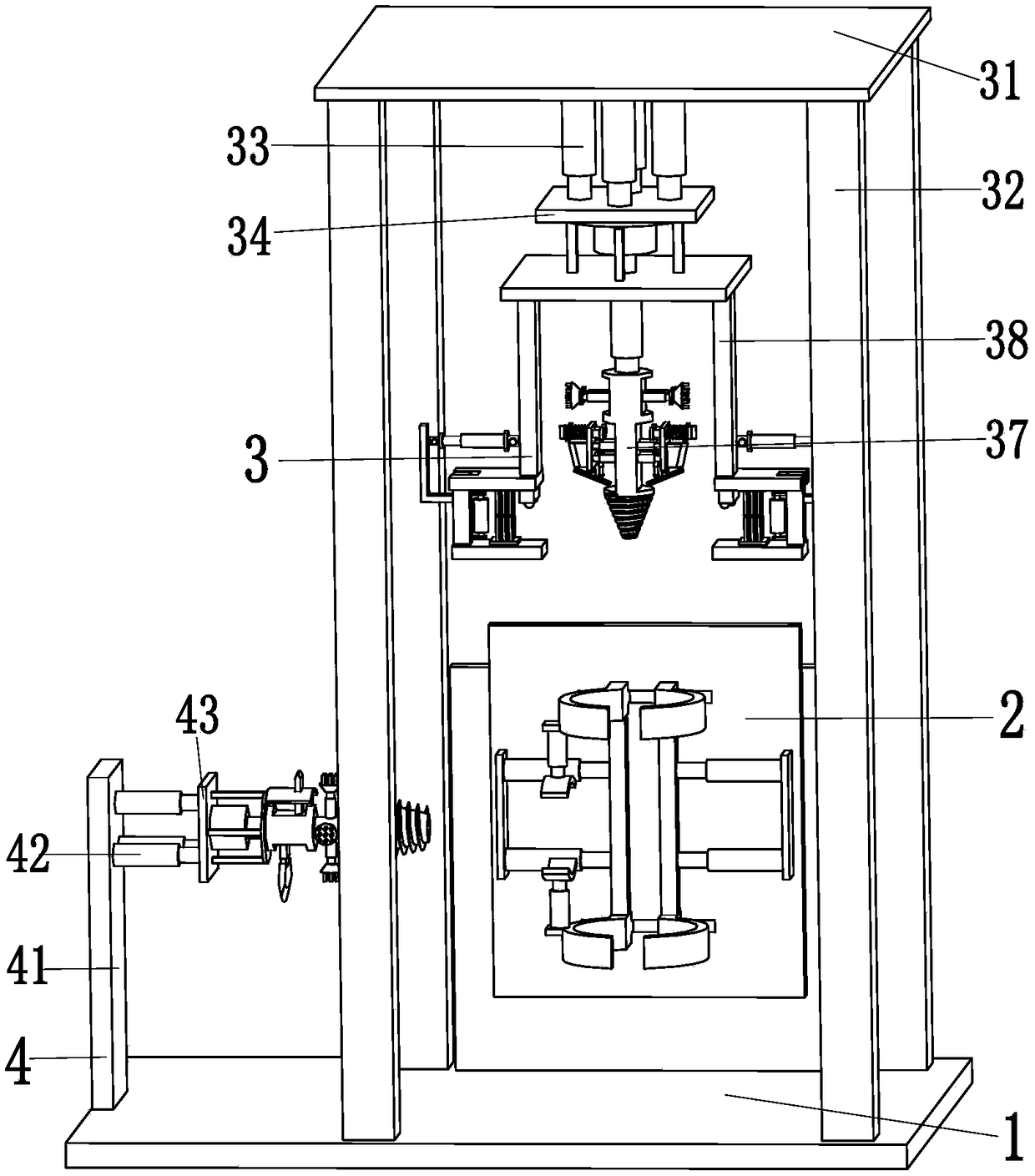
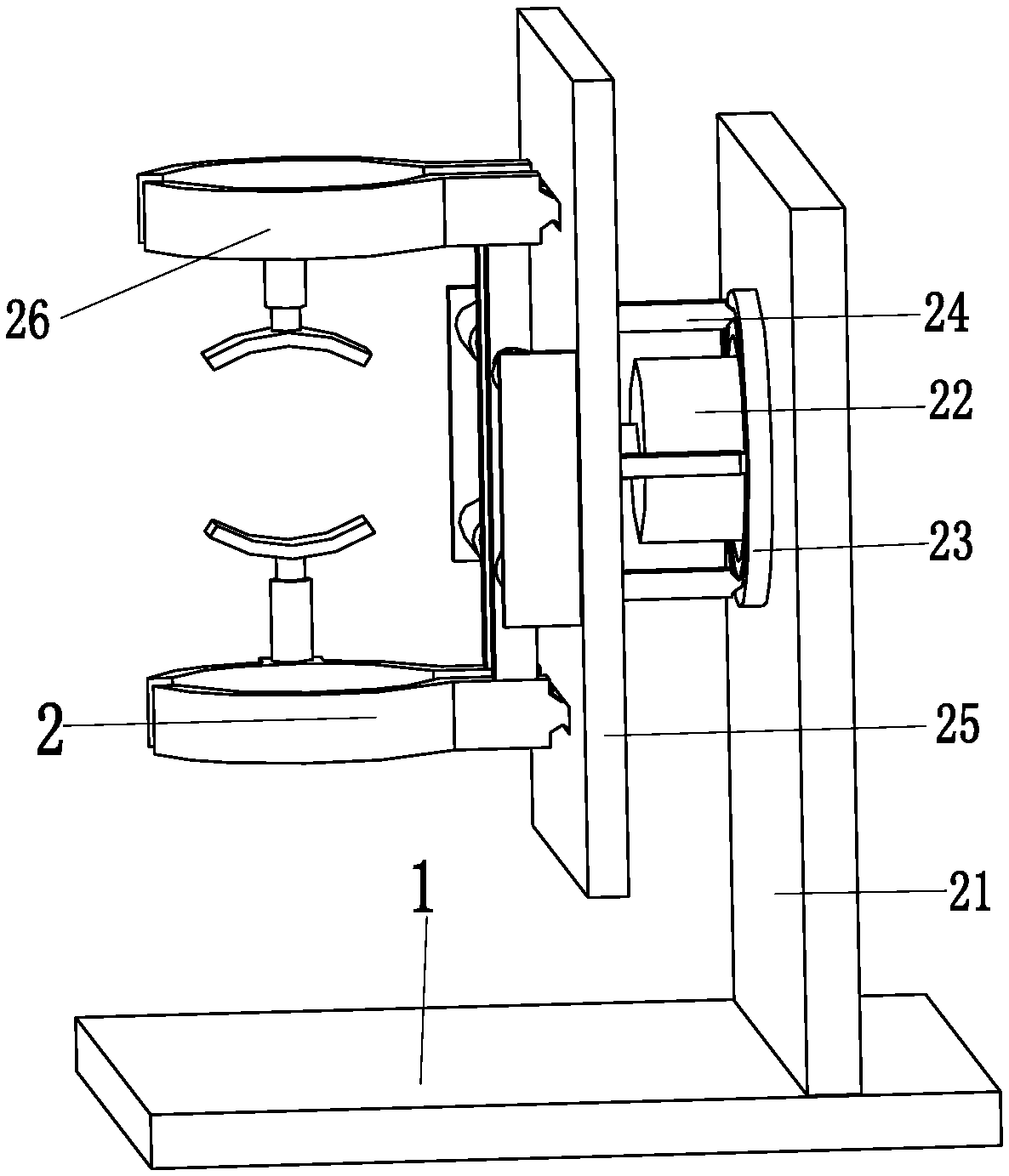
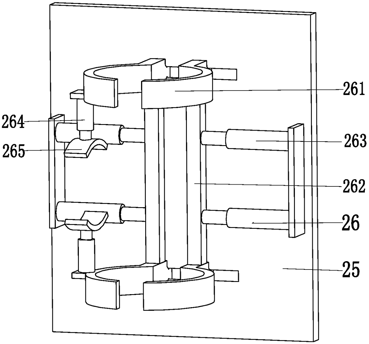
[0030] Such as Figure 1 to Figure 8 As shown, a three-way flange pipe automatic clamping and cleaning equipment includes a support base plate 1, a clamping device 2, a cleaning device 3 and a side cleaning device 4, and a clamping device is installed on the top of the rear end of the support base plate 1. Device 2, the cleaning device 3 is located at the upper end of the clamping device 2, the cleaning device 3 is installed on the top of the support base 1, the side cleaning device 4 is located on the left side of the clamping device 2, and the side cleaning device 4 is installed on...


PUM


Abstract

The invention relates to automatic clamping and cleaning equipment for a tee flange pipe. The automatic clamping and cleaning equipment comprises a supporting bottom plate, a clamping device, a cleaning device and a lateral cleaning device. The clamping device is mounted at the top of the rear end of the supporting bottom plate, the cleaning device is located at the upper end of the clamping device, and the cleaning device is mounted at the top of the supporting bottom plate. The lateral cleaning device is located on the left side of the clamping device and mounted at the top of the supportingbottom plate. The clamping device comprises clamping side plates, a clamping motor, a clamping slide groove, a clamping slide rod, a clamping rotating plate and a clamping mechanism. The automatic clamping and cleaning equipment can solve the problems that when sand in an existing tee flange pipe is removed, manual labor intensity is high, a tee cannot be clamped and fixed according to the structure of the tee, a straight pipe of the tee needs to be manually cleaned, the cleaning effect of the straight pipe of the tee is poor, the straight pipe of the tee and a flange cannot be synchronouslycleaned, and lateral pipes of the tee are high in cleaning difficulty and cannot be completely cleaned.

Description

technical field [0001] The invention relates to the technical field of municipal material processing, in particular to an automatic clamping and cleaning device for a three-way flange pipe. Background technique [0002] Municipal tee flange pipes are generally processed by casting. After the tee flange pipe is cast, the sand in the tee pipe needs to be cleaned. Since the casting is basically carried out by vacuum casting Production, so that the sand in the tee flange pipe cannot be removed by simple vibration operation. It is necessary to use a semi-automatic method to clean the sand in the tee pipe. First, the tee pipe is locked and fixed, and then manually through the drill bit and cleaning Brush to clean the sand in the tee flange pipe. The problems of this kind of work are as follows. Manual operation causes high labor intensity, and it cannot be clamped and fixed according to the structure of the tee pipe. The unstable clamping affects the tee pipe. The cleaning effect...

Claims


Application Information

Patent Timeline
Patent Type & Authority Applications(China)
IPC IPC(8): B22D31/00
CPCB22D31/002
Inventor 蔡建丰
Owner SHANDONG LIANGSHAN TONGYA AUTOMOBILE MFG CO LTD
Why Eureka
Try Eureka