
Shaft type workpiece floating clamping and driving device for four-axis machining center

A technology for four-axis machining centers and shaft workpieces, which is applied to metal processing machinery parts, positioning devices, metal processing equipment, etc., can solve the problems of high precision, long clamping time, and large positioning errors, and achieve The effect of improving the processing efficiency of the equipment, high precision of rotation indexing, and fast driving indexing speed

Active Publication Date: 2019-01-11
重庆升科精锻科技有限公司
View PDF13 Cites 2 Cited by
  • Summary
  • Abstract
  • Description
  • Claims
  • Application Information

AI Technical Summary

Problems solved by technology

Conventional shaft products will have the following problems when they are processed on a four-axis vertical machining center: 1. There are two conversions in this clamping method, the positioning error is large, and the machining accuracy cannot meet the needs of high precision; 2. The clamping time is long, and the clamping installation and disassembly after processing of each workpiece need to be carried out separately, which consumes more time and lower processing efficiency

Method used


Image

  • Shaft type workpiece floating clamping and driving device for four-axis machining center

Examples


Embodiment Construction

[0013] Below in conjunction with accompanying drawing and specific embodiment, the present invention is described further;

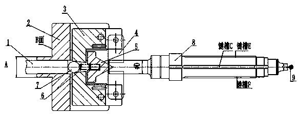
[0014] Such as figure 1 As shown, the four-axis machining center shaft workpiece floating clamping drive device of the present invention includes a support body 2 and a rotating arm 3, the rotating arm 3 is rotatable, and is movable between the support body 2; on the support body 2 , a hole is arranged horizontally, the ejector rod 1 passes through the hole transversely, and a pushing device is arranged at the rear end of the ejector rod 1, which can be a commonly used hydraulic cylinder, air cylinder, etc., and an active force is applied to push the ejector rod 1 to move laterally; Corresponding to the position of the ejector rod 1, the arm 3 is provided with a transverse tapered hole with a large outer diameter and a smaller inner diameter, and a steel ball 7 is arranged in the tapered hole; the steel ball 7 is provided with a compression spring for re...


PUM


Abstract

The invention discloses a shaft type workpiece floating clamping and driving device for a four-axis machining center. The shaft type workpiece floating clamping and driving device comprises a supporting body and a rotating arm which is rotatable; a hole is transversely formed in the supporting body; an ejection rod is transversely moved to transversely penetrate through the hole; a transverse tapered hole is formed in the rotating arm; a steel ball is fit in the tapered hole; a pressure spring for return is arranged on the steel ball; clamping arms are arranged at the front end of the rotatingarm; after being pushed by the ejection rod, the steel ball pushes the rotating arm to drive the clamping arms to radially move toward the center, generating acting force for clamping; a center tip is arranged on the inner side of the front end of the rotating arm and correspondingly fit with the positions of the clamping arms; and the center lines of the ejection rod, the steel ball and the center tip are located at the same horizontal line. By means of the shaft type workpiece floating clamping and driving device, the problem that the excircle of a to-be-machined shaft type product and a center hole are not coaxial can be solved, and the effect that two clamping jaws clamp the excircle in a floating manner in the case that the center hole is centered can still be achieved. The shaft type workpiece floating clamping and driving device can obtain very high machining precision and improve the machining efficiency of equipment.

Description

technical field [0001] The patent of the present invention relates to a clamping drive structure for processing parts with symmetrical central axes, especially a floating clamping drive device for axial workpieces in four-axis machining centers. Background technique [0002] The four-axis vertical machining center is a general-purpose mechanical processing equipment. The four-axis is based on the X, Y, and Z axes, and the linkage electric indexing device is added, which can conveniently process the axisymmetric parts of the center (axis workpieces) ) The shape and size of the outer circle in different angular directions. At present, when shaft parts are processed with the center hole as the reference, the usual practice is that the two tops withstand the center hole, install a chicken heart clamp on the outer circle of the shaft to clamp the product, and then connect the chicken heart clamp to the end face of the turntable to ensure that the shaft and 4 The axis turntable h...

Claims


Application Information

Patent Timeline
Patent Type & Authority Applications(China)
IPC IPC(8): B23Q3/12
CPCB23Q3/12
Inventor 敬勇苏涛高凤强高章红胡斌
Owner 重庆升科精锻科技有限公司
Learn More