Flowing friction additional material manufacturing device and additional material manufacturing method

A technology of additive manufacturing and flow friction, applied in the field of additive manufacturing, can solve the problems of large machining allowance and low material utilization rate, and achieve the effects of low material utilization rate, high efficiency, low-cost manufacturing, and material structure refinement

Active Publication Date: 2019-01-15
AVIC BEIJING AERONAUTICAL MFG TECH RES INST
View PDF8 Cites 16 Cited by
  • Summary
  • Abstract
  • Description
  • Claims
  • Application Information

AI Technical Summary

Problems solved by technology

[0006] In order to solve the problems existing in the prior art, the present invention provides a flow friction additive manufacturing device and additive manufacturing method, which can realize high-quality additive manufacturing of light metal materials such as aluminum alloys, and can improve material utilization and manufacturing High efficiency, which solves the problems of large machining allowance and low material utilization in friction stir additive manufacturing

Method used


Image

  • Flowing friction additional material manufacturing device and additional material manufacturing method
  • Flowing friction additional material manufacturing device and additional material manufacturing method

Examples


Embodiment 1

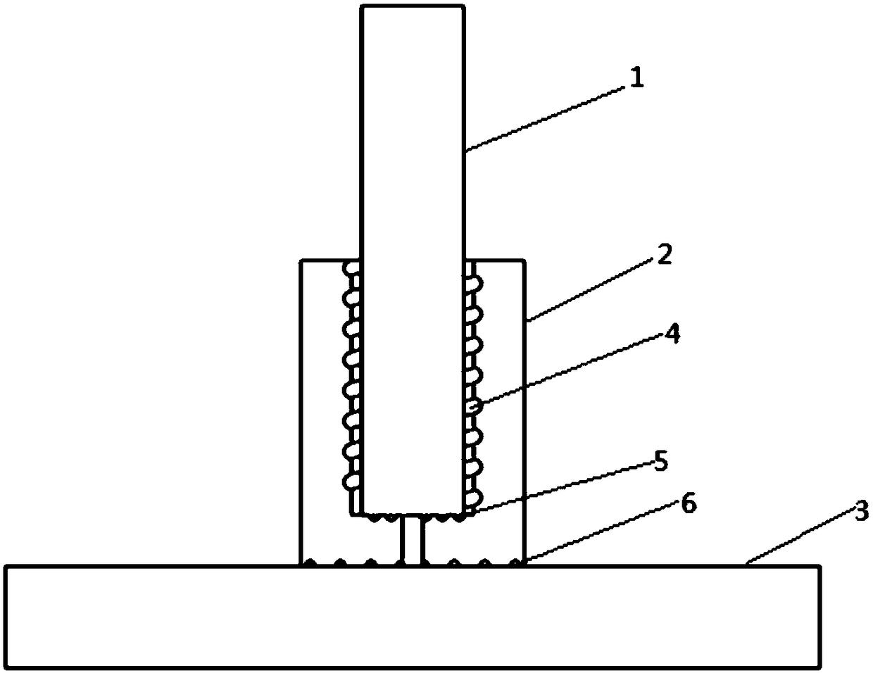
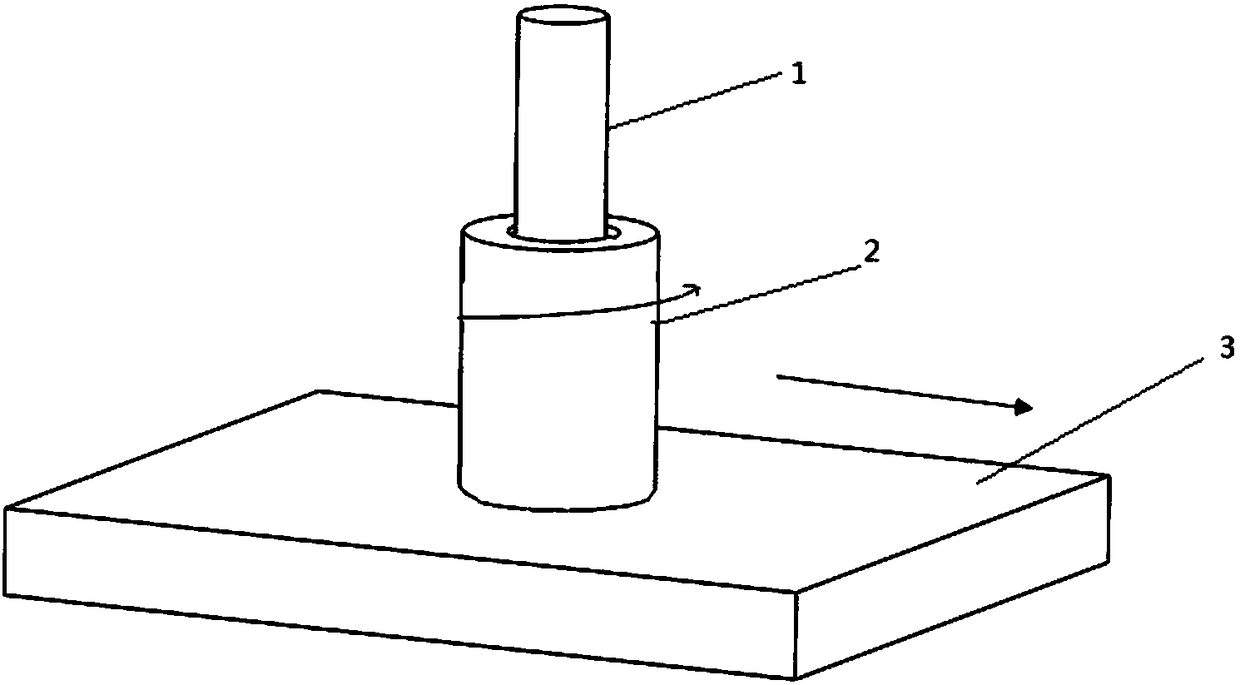
[0032] Such as figure 1 As shown, a flow friction additive manufacturing device includes a shoulder 2, a base material 1 and a base 3, the shoulder 2 is cylindrical, the base material 1 is also cylindrical, and the base 3 is a plate with a cavity inside the shoulder , the lower end of the shaft shoulder below the cavity is provided with a central through hole communicating with the cavity, the cylindrical base material is placed in the cavity inside the shaft shoulder, and the outer end surface of the shaft shoulder is placed on the surface of the matrix to be added; The side wall of the cavity is designed with a spiral groove, that is, the spiral groove 4 on the side wall of the cavity, and the bottom surface of the cavity is also designed with a spiral groove, that is, the spiral groove 5 on the bottom surface of the cavity. The rotation direction of the spiral groove structure depends on the rotation direction of the shoulder during the additive manufacturing process, and c...


PUM


Abstract

The invention relates to a flowing friction additional material manufacturing device and an additional material manufacturing method. The additional material manufacturing device comprises a shaft shoulder, a mother material and a base body. A cavity is formed in the shaft shoulder. A center through hole communicating with the cavity is formed in the lower end, below the cavity, of the shaft shoulder. The mother material is placed in the cavity in the shaft shoulder. Upsetting force exists between the mother material and the bottom face of the cavity in the shaft shoulder. Upsetting force exists between the shaft shoulder and the base body. In the additional material manufacturing process, the shaft shoulder rotates and moves on the surface, with materials to be added, of the base body, the mother material does not rotate, the mother material is subjected to heat plastification under the friction effect, the material subjected to heat plastification flows out along the center through hole in the lower end of the shaft shoulder under the effect of the upsetting force, and under the relative rotating effect of the outer end face of the shaft shoulder and the surface, with the materials to be added, of the base body, and under the upsetting force effect, the material is dispersed and deposited on the surface, with the materials to be added, of the base body. According to the device and the method, the material utilization rate can be increased, the manufacturing efficiency can be improved, and the problems that the working allowance of stirring friction additional material manufacturing is large, and the material utilization rate is low are solved.

Description

technical field [0001] The invention relates to a flow friction additive manufacturing device and an additive manufacturing method, belonging to the technical field of additive manufacturing. Background technique [0002] Additive Manufacturing (AM) is to pre-establish and plan 3D models through computer technology, combined with digital controllable heat sources to melt, clad or superimpose materials layer by layer, and rapidly form structural or functional parts. The five technical characteristics of dimensional manufacturing, stacking manufacturing, direct manufacturing, and rapid manufacturing have attracted widespread attention from all over the world, bringing a series of profound changes to traditional manufacturing, and can be widely used in aerospace, national defense, medical, architectural design, and automobile manufacturing. and other fields. [0003] The commonly used metal additive manufacturing methods include laser, electron beam and electric arc additive m...

Claims


Application Information

Patent Timeline
Patent Type & Authority Applications(China)
IPC IPC(8): B23K20/12B33Y10/00B33Y30/00
CPCB23K20/1215B33Y10/00B33Y30/00
Inventor 赵华夏王卫兵
Owner AVIC BEIJING AERONAUTICAL MFG TECH RES INST
Why Eureka
Try Eureka