
Anti-collision beam for unmanned vehicle, being able to sufficiently absorb impact stress

An unmanned vehicle, impact stress technology, applied in the direction of the bumper, can solve the problems of poor impact absorption effect, limited energy absorption, poor protection effect, etc., to achieve good protection effect and good energy absorption effect

Inactive Publication Date: 2019-01-11
唐燕
View PDF6 Cites 10 Cited by
  • Summary
  • Abstract
  • Description
  • Claims
  • Application Information

AI Technical Summary

Problems solved by technology

[0003] The technical problem solved by the present invention is to overcome the defects of the prior art such as poor impact absorption effect, limited energy absorption and poor protection effect, and provide an anti-collision beam for unmanned vehicles that can fully absorb impact stress

Method used

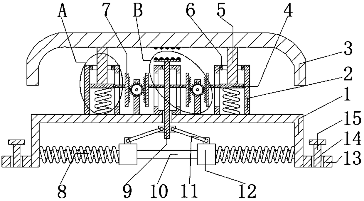

Image

  • Anti-collision beam for unmanned vehicle, being able to sufficiently absorb impact stress
  • Anti-collision beam for unmanned vehicle, being able to sufficiently absorb impact stress
  • Anti-collision beam for unmanned vehicle, being able to sufficiently absorb impact stress

Examples


Embodiment Construction

[0014] The following will clearly and completely describe the technical solutions in the embodiments of the present invention with reference to the accompanying drawings in the embodiments of the present invention. Obviously, the described embodiments are only some, not all, embodiments of the present invention. Based on the embodiments of the present invention, all other embodiments obtained by persons of ordinary skill in the art without making creative efforts belong to the protection scope of the present invention.

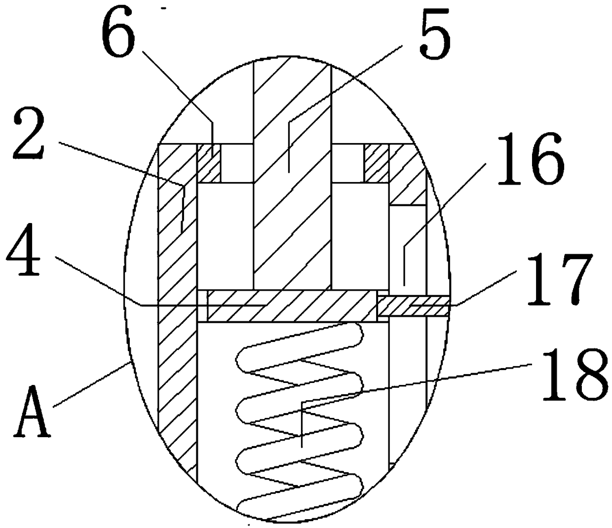
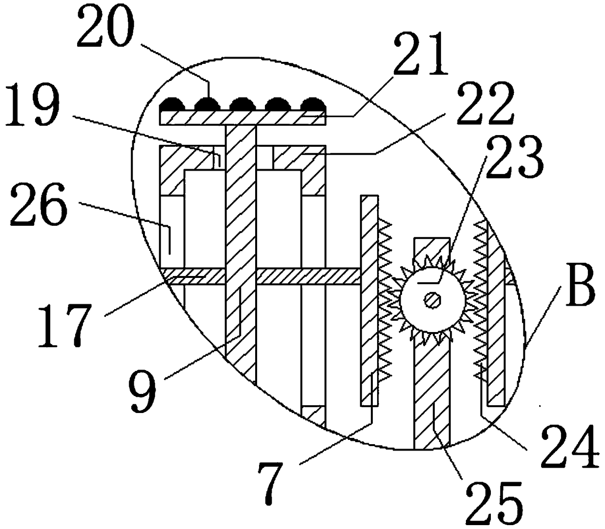
[0015] see Figure 1-3 , the present invention provides a technical solution: an anti-collision beam for an unmanned vehicle that can fully absorb impact stress, including a U-shaped mounting frame 1 and an anti-collision plate 3, the U-shaped mounting frame 1 is opened downward, and the U-shaped The top of the mounting frame 1 is fixedly connected with thick tubes 2 near both sides, and the two thick tubes 2 are provided with compression springs 18. The botto...


PUM


Abstract

The invention discloses an anti-collision beam for an unmanned vehicle, being able to sufficiently absorb impact stress, including a U-shaped mounting bracket, an anti-collision plate, tension springsand compression springs, wherein the U-shape mounting bracket has an opening face downward; the top, close to two sides, of the U-shape mounting bracket is fixedly connected with thick pipes; the compression springs are arranged in the two thick pipes; the bottom end of the each compression spring is fixedly connected with the top of the U-shaped mounting bracket; a movable block is fixedly connected with the top end of the each compression spring; the movable block is slidably connected with the inner wall of the thick pipe; a thin rod is fixedly connected to the top of the movable block; the top end of the thin rod passes through the nozzle of the top of the thick pipe, and extends to the outside of the thick pipe to be fixedly connected with the bottom of the anti-collision plate; a mounting box is arranged between the two thick pipes; the bottom of the mounting box is fixedly connected with the top of the U-shaped mounting bracket; vertical rods are arranged in the mounting box; and through holes matching with the vertical rods are formed in the top and bottom of the mounting box and the U-shaped mounting bracket.

Description

technical field [0001] The invention relates to the technical field of anti-collision beams for vehicles, in particular to an anti-collision beam for unmanned vehicles that can fully absorb impact stress. Background technique [0002] With the advancement of technology and the development of social economy, automobiles have gradually become an important tool for people's life and travel. A large number of automobiles have entered family life, and the increase in the number of automobiles has also resulted in an increase in the number of traffic accidents. In traffic accidents, frontal collision is a relatively common form of collision. As a product of new technology, driverless cars have also entered people's lives. As an important part of vehicle safety systems, anti-collision beams can When a collision occurs, it will deform itself to absorb the collision force, and the buffer components such as the energy-absorbing box arranged on the rear side of the anti-collision beam ...

Claims


Application Information

Patent Timeline
IPC IPC(8): B60R19/02B60R19/18
CPCB60R19/02B60R19/18
Inventor 唐燕
Owner 唐燕
Learn More