
Chemical oxygen production apparatus

An oxygen production device and chemical technology, applied in the direction of inorganic chemistry, chemical instruments and methods, oxygen/ozone/oxide/hydroxide, etc., can solve the problems of low oxygen production efficiency, inability to produce a large amount of oxygen, complex structure, etc. , to achieve the effect of easy promotion, convenient use and large contact area

Pending Publication Date: 2019-01-11
刘笑菲
View PDF3 Cites 0 Cited by
  • Summary
  • Abstract
  • Description
  • Claims
  • Application Information

AI Technical Summary

Problems solved by technology

[0002] In the chemical oxygen production process, the oxygen generation rate is related to the concentration of hydrogen peroxide and the contact area between hydrogen peroxide and manganese dioxide. The oxygen production equipment in the prior art has a complex structure and relatively low oxygen production efficiency. Unable to produce a large amount of oxygen quickly and conveniently

Method used


Image

  • Chemical oxygen production apparatus
  • Chemical oxygen production apparatus
  • Chemical oxygen production apparatus

Examples


Embodiment 1

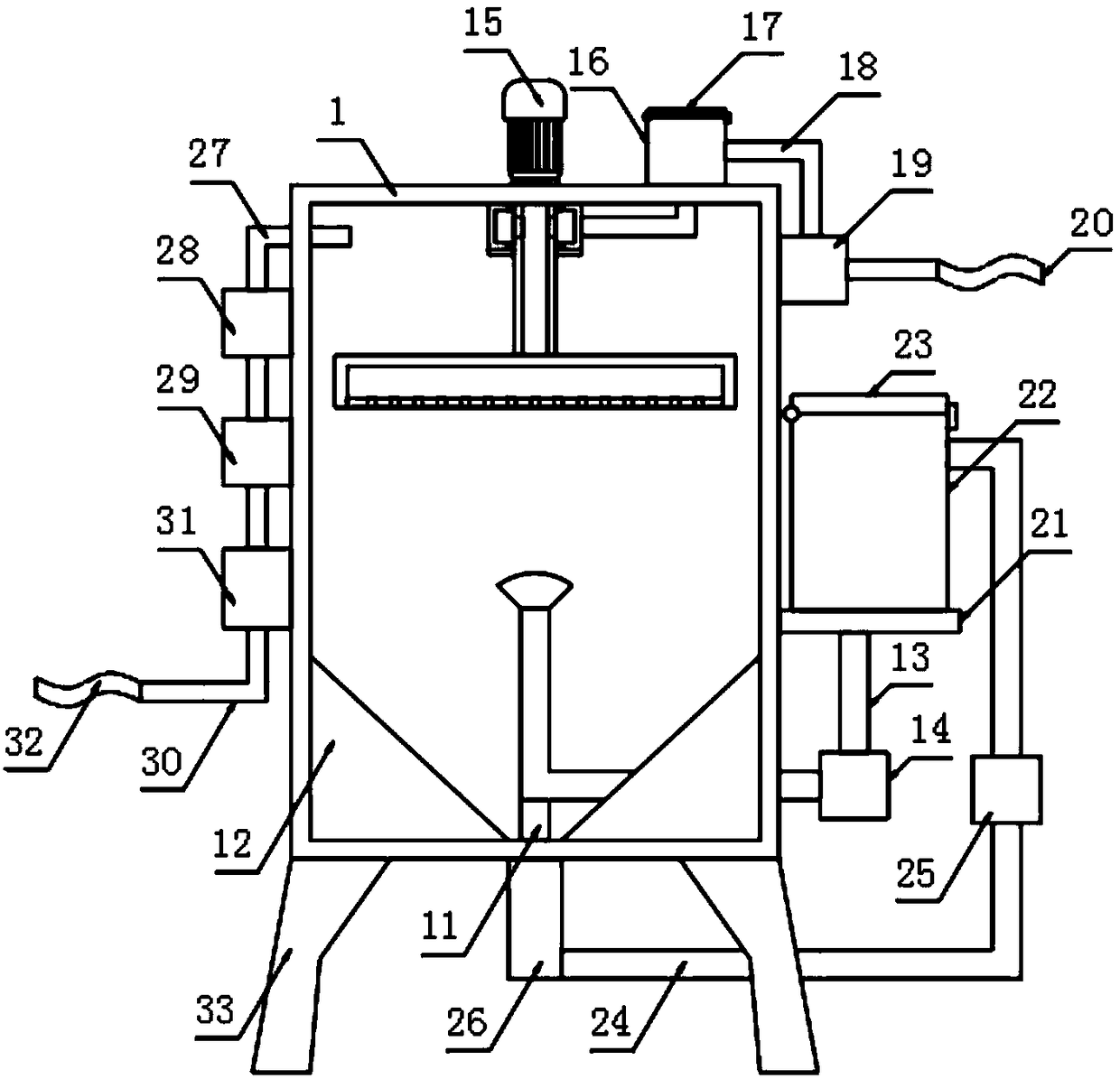
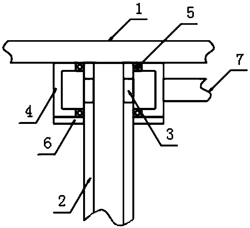
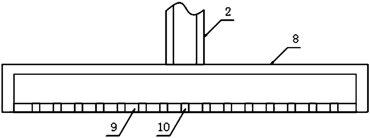
[0026] The present invention provides such as Figure 1-5 The shown chemical oxygen production device includes a reaction chamber 1, a hollow rotating rod 2 runs through the top of the reaction chamber 1, and a feed hole 3 runs through the side wall of the hollow rotating rod 2. The outer side of the rotating rod 2 is sleeved with a connecting chamber 4, and the side of the connecting chamber 4 is provided with a first feed pipe 7, and the bottom end of the hollow rotating rod 2 is fixed with a diverging chamber 8, and the bottom of the diverging chamber 8 is embedded A partition 9 is sleeved, and a through hole 10 is formed on the partition 9. A placement seat 11 is fixed at the bottom of the inner cavity of the reaction chamber 1, and a liquid inlet pipe 13 is fixed at the top of the placement seat 11. The top of the liquid inlet pipe 13 is fixed with a shower head 38, the liquid inlet pipe 13 is provided with a first booster pump 14, the top of the reaction chamber 1 is fix...

Embodiment 2

[0029] Further, in the above-mentioned embodiment 1, the connecting chamber 4 is fixedly arranged on the top of the inner cavity of the reaction chamber 1, and a bearing 5 is provided between the hollow rotating rod 2 and the connecting chamber 4, and the inner side of the bearing 5 is connected with the hollow rotating rod. The rod 2 is fixedly connected, the outer side of the bearing 5 is fixedly connected with the connection cavity 4 , and the bottom of the connection cavity 4 is fixedly provided with a sealing plate 6 .

[0030] Further, in the above-mentioned embodiment 1, the bottom of the inner cavity of the reaction chamber 1 is fixed with a flow guide block 12, the flow guide block 12 is arranged on the outside of the placement seat 11, and the top of the flow guide block 12 is provided with a flow guide block. The section of the diversion groove is set as an inverted isosceles trapezoid, so that the unreacted hydrogen peroxide slides down along the diversion block 12,...


PUM


Abstract

The invention discloses a chemical oxygen production apparatus. The chemical oxygen production apparatus includes a reaction chamber, a hollow rotating rod passes through a top end of the reaction chamber, a feed port passes through an outer side of the hollow rotating rod, a connecting chamber is sleeved on the outer side of the hollow rotating rod, a first feeding tube passes through a side surface of the connecting chamber, the bottom of the hollow rotating rod is fixedly provided with a diverging cavity, a separator plate is embedded in the bottom of the diverging cavity, a through hole passes through the separator plate, the bottom of the inner cavity of the reaction chamber is fixedly provided with a placing seat, the top of the placing seat is fixedly provided with a liquid inlet pipe, the top of the liquid inlet pipe is fixedly provided with a shower head, and the liquid inlet pipe is provided with a first boosting pump. The apparatus increases a lateral area in the dropping process of manganese dioxide and makes the sprayed hydrogen peroxide to a divergent state, so that the manganese dioxide has a great contact area with the hydrogen peroxide, and a reaction can be carried out in a very short time and oxygen is generated, so that the chemical oxygen production apparatus has the advantages of convenient usage and high oxygen production efficiency.

Description

technical field [0001] The invention relates to the technical field of chemical oxygen production, in particular to a chemical oxygen production device. Background technique [0002] In the chemical oxygen production process, the oxygen generation rate is related to the concentration of hydrogen peroxide and the contact area between hydrogen peroxide and manganese dioxide. The oxygen production equipment in the prior art has a complex structure and relatively low oxygen production efficiency. It is impossible to produce a large amount of oxygen relatively quickly and conveniently. [0003] Therefore, it is necessary to invent a chemical oxygen generator to solve the above problems. Contents of the invention [0004] The object of the present invention is to provide a kind of chemical oxygen generator, by making the lateral area in the falling process of manganese dioxide increase and the hydrogen peroxide after spraying is divergent, so manganese dioxide and hydrogen pero...

Claims


Application Information

Patent Timeline
IPC IPC(8): C01B13/02
CPCC01B13/0214
Inventor 刘笑菲
Owner 刘笑菲
Learn More