A high-efficiency steel bar cutting machine

A cutting machine and steel bar technology, applied in the directions of cleaning methods and utensils, chemical instruments and methods, cleaning methods using tools, etc., can solve the problems of enlarged cross-sectional surface area of ​​steel bars, difficult to cut, etc., to avoid the lateral area Amplify, enhance the effect, prevent damage to the effect too quickly

Active Publication Date: 2021-11-05
山东振鹏建筑钢品科技有限公司
View PDF5 Cites 0 Cited by
  • Summary
  • Abstract
  • Description
  • Claims
  • Application Information

AI Technical Summary

Problems solved by technology

[0002] The steel bar cutting machine is used for the fixed-length cutting of steel bars, and is suitable for ordinary carbon steel, hot-rolled round steel and screw steel in various reinforced concrete in construction engineering. It has the advantages of small size, light weight, strong and reliable, and is convenient for construction However, when the previous equipment cuts the steel bar, the steel bar will rub against the cutting blade, sparks will be sputtered, and part of the high-temperature chip residue will be adhered to the splashed sparks. Continuous contact with oxygen causes its surface to oxidize and the internal temperature continues to be high, and the flying sparks will change the jet direction with the airflow of the cutting blade. Since there is a certain gap between the cutting blade and the baffle, the airflow flows here Cyclone air flow will be formed when the steel bar is cut, so that the high-temperature chip residue in the spark will reattach to the surface of the cutting blade along with the air flow, so that the lateral area of ​​the cutting blade surface will expand, and when the steel bar is cut, the force-bearing area of ​​the cross-sectional surface of the steel bar will become larger. Difficult to cut, causing the blade to slip on rebar surfaces

Method used


Image

  • A high-efficiency steel bar cutting machine
  • A high-efficiency steel bar cutting machine
  • A high-efficiency steel bar cutting machine

Examples


Embodiment 1

[0023] like Figure 1-Figure 5 Shown:

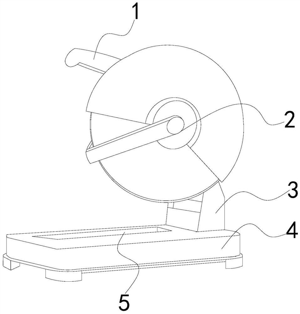
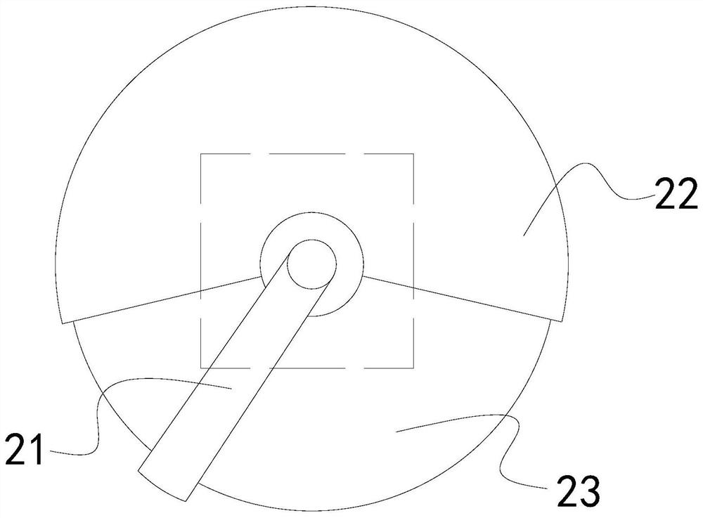
[0024] A high-efficiency steel bar cutting machine of the present invention, its structure includes pressing handle 1, rotating mechanism 2, fixing base 3, placing plate 4, cutting hole 5, described rotating mechanism 2 is installed on the right side of fixing base 3, described pressing handle 1 is located on the upper end of the fixing seat 3, the fixing seat 3 is welded on the surface of the placing plate 4, the cutting hole 5 is located in the middle of the placing plate 4, the pressing handle 1 is installed on the left side of the rotating mechanism 2, the rotating Mechanism 2 is provided with cleaning device 21, protective shell 22, cutting blade 23, and the upper end of described cleaning device 21 is embedded in the central point of cutting blade 23, and described protective shell 22 and cutting blade 23 are located on the same central axis, and described Protective shell 22 is installed in the middle of fixed seat 3, and describ...

Embodiment 2

[0031] like Figure 6-Figure 7 Shown:

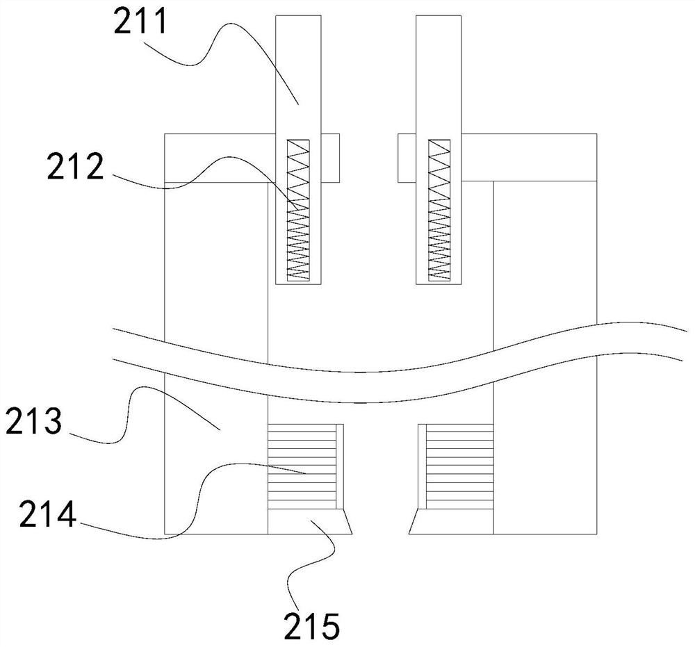
[0032]Wherein, the cleaning mechanism 215 is composed of a cleaning plate e1, a balance bar e2, a first elastic bar e3, a fixed bar e4, a second elastic bar e5, a fixed block e6, and a stressed bar e7. Fixed in the middle of the cleaning plate e1, the left side of the balance bar e2 is attached to the upper and lower ends of the cleaning plate e1, the first elastic rod e3 is installed on the right side of the balance bar e2, and the first elastic bar e3 The right end of the fixed rod e6 is installed on the left side of the fixed block e6, the middle of the first elastic rod e3 is embedded in the upper and lower ends of the force rod e7, and the right end of the fixed rod e4 is attached to the left side of the second elastic rod e5 , the upper end of the fixed block e6 is attached to the lower end of the scraping mechanism 214, the cleaning plate e1 is in an inclined shape, which makes the cut of the cutting blade rub and makes it sharpe...


PUM


Abstract

The invention discloses a high-efficiency steel bar cutting machine. Its structure includes a pressing handle, a rotating mechanism, a fixed seat, a placement plate, and a cutting hole. The rotating mechanism is provided with a cleaning device, a protective shell, and a cutting blade. On the left and right sides of the blade, the spring rod shrinks the scraper to avoid friction between the scraper and the cutting blade at all times, preventing the scraper from being damaged too quickly, and the magnetic blocks on the upper and lower sides of the spring rod keep the spring rod in balance, scraping The cleaning mechanism at the lower end of the cleaning mechanism makes the cutting blade more sharp. The inclined cleaning plate is stretched and stretched through the second elastic rod at the right end of the fixed rod, which rubs against the cut of the cutting blade, and the cleaning rod on the cleaning plate acts on the cut of the cutting blade. Force, to avoid the expansion of the lateral area of ​​the cutting blade surface, block cleaning block to scrape off the swarf residue attached to the side of the cutting blade, to prevent the swarf residue from solidifying on the side of the cutting blade after cooling, and to prevent the cutting blade from slipping on the surface of the steel bar when cutting.

Description

technical field [0001] The invention relates to the construction field, in particular to a high-efficiency steel bar cutting machine. Background technique [0002] The steel bar cutting machine is used for the fixed-length cutting of steel bars, and is suitable for ordinary carbon steel, hot-rolled round steel and screw steel in various reinforced concrete in construction engineering. It has the advantages of small size, light weight, strong and reliable, and is convenient for construction However, when the previous equipment cuts the steel bar, the steel bar will rub against the cutting blade, sparks will be sputtered, and part of the high-temperature chip residue will be adhered to the splashed sparks. Continuous contact with oxygen causes its surface to oxidize and the internal temperature continues to be high, and the flying sparks will change the jet direction with the airflow of the cutting blade. Since there is a certain gap between the cutting blade and the baffle, t...

Claims


Application Information

Patent Timeline
Patent Type & Authority Patents(China)
IPC IPC(8): B21F11/00B08B1/02B08B1/00
CPCB08B1/001B08B1/02B21F11/00
Inventor 黄桂英
Owner 山东振鹏建筑钢品科技有限公司
Why Eureka
Try Eureka