Sludge treatment device

A technology of sludge treatment and support plate, which is applied in the direction of sludge treatment, water/sludge/sewage treatment, chemical instruments and methods, etc. It can solve the problems of short service life of the machine and timing treatment of the sludge.

Inactive Publication Date: 2019-01-11
乔晓雪
View PDF5 Cites 6 Cited by
  • Summary
  • Abstract
  • Description
  • Claims
  • Application Information

AI Technical Summary

Problems solved by technology

The drum of the sludge centrifuge of the utility model is arranged horizontally, which can ensure more uniform and sufficient dehydration of the sludge, so as to reduce the volume of the sludge and realiz...

Method used


Image

  • Sludge treatment device
  • Sludge treatment device
  • Sludge treatment device

Examples


specific Embodiment approach 1

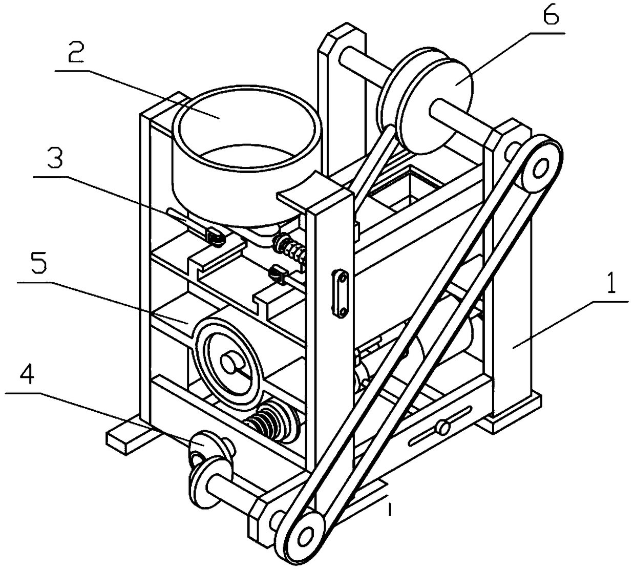
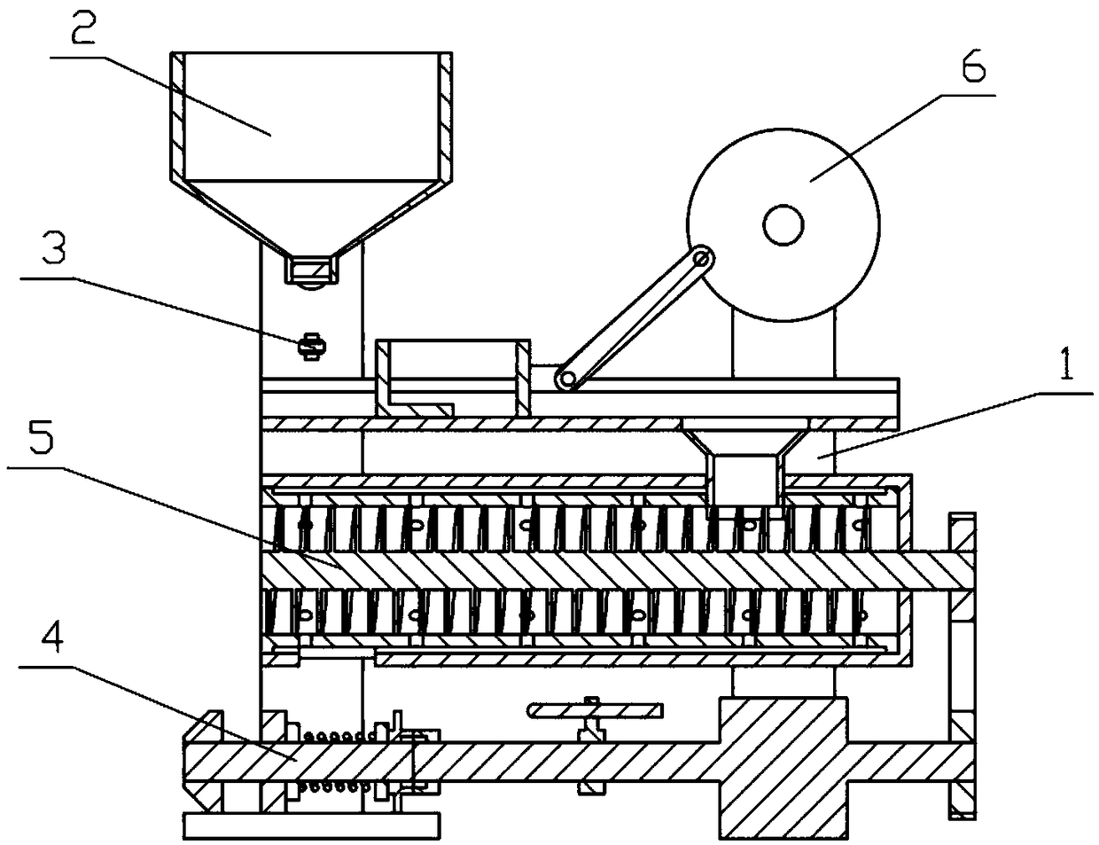
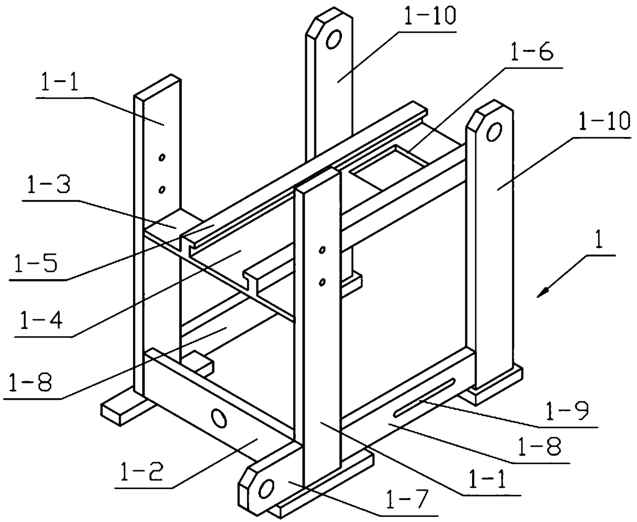
[0031] Combine below Figure 1-11 Describe this embodiment, a sludge treatment device, including a complete machine support 1, a discharge support 2, a closing mechanism 3, a power mechanism 4, a dehydration mechanism 5 and a feeding mechanism 6, which can pass through the threaded cylinder 4 set on the power mechanism 4 -4. The sliding column 4-5 and the threaded column 4-6 realize the timing transmission of the motor 4-1 to the friction wheel II 4-8, and control the working time of the feeding mechanism 6 by controlling the rotation time of the friction wheel II 4-8 to realize timing work , the machine can stop working automatically in the absence of manpower; the diameter of the dehydration pulley 5-6 is greater than the diameter of the power pulley 4-2 so that the power transmitted on the motor 4-1 can be applied to the dehydration mechanism 5 to work, dehydration The mechanism 5 can separate the sludge and water, and the reciprocating motion of the feeding mechanism 6 pus...


PUM


Abstract

The invention relates to the field of sludge purification, and concretely relates to a sludge treatment device. The sludge treatment device comprises a whole machine bracket, a discharge bracket, a closing mechanism, a power mechanism, a dewatering mechanism and a feeding mechanism. The timing transmission of a friction wheel II by a motor is realized through a threaded cylinder, a sliding columnand a threaded column which are arranged on the power mechanism, and the working time of the feeding mechanism is controlled by controlling the rotation time of the friction wheel II in order to realize timing work, so the device can stop working by itself in the absence of a worker; and the diameter of a dewatering belt pulley is larger than the diameter of a power belt pulley to make the power transmitted by the motor suitable for the dewatering mechanism to work, the dewatering mechanism can separate sludge and water, and the reciprocating motion of the feeding mechanism pushes the closingmechanism to drive the discharge bracket to close and open in order to achieve intermittent feeding and prevent the influences of excessive sludge in the dewatering mechanism due to continuous feedingon the dewatering effect and the life of the device.

Description

technical field [0001] The invention relates to the field of sludge purification, in particular to a sludge treatment device. Background technique [0002] For example, the publication number CN207227252U discloses a sludge treatment device, which belongs to the technical field of sludge treatment. A sludge treatment device, comprising a sludge centrifuge with a sludge inlet and a sludge outlet and a water collection shell; the sludge centrifuge is a horizontal drum driven by a motor, and the side wall of the drum is set A number of drainage holes, the outside of the drum is covered with a permeable membrane, and the inside of the sludge centrifuge is equipped with a stirring plate at an angle to the axis; the sludge centrifuge is installed inside the water collection shell, and the lower end of the water collection shell is provided with drainage holes. The drum of the sludge centrifuge of the utility model is arranged horizontally, which can ensure more uniform and suffic...

Claims


Application Information

Patent Timeline
IPC IPC(8): C02F11/121
CPCC02F11/121
Inventor 乔晓雪
Owner 乔晓雪
Why Eureka
Try Eureka