

An adjustment device for engineering hydraulic support
A technology of hydraulic support and adjustment device, which is applied in mine roof support, mining equipment, earthwork drilling and mining, etc., which can solve the problems of inability to adjust the pitch angle of hydraulic support and limit construction efficiency, and achieve convenient adjustment, simple operation and convenient use Effect
- Summary
- Abstract
- Description
- Claims
- Application Information
AI Technical Summary
Problems solved by technology
Method used
Image

Examples
Embodiment 1
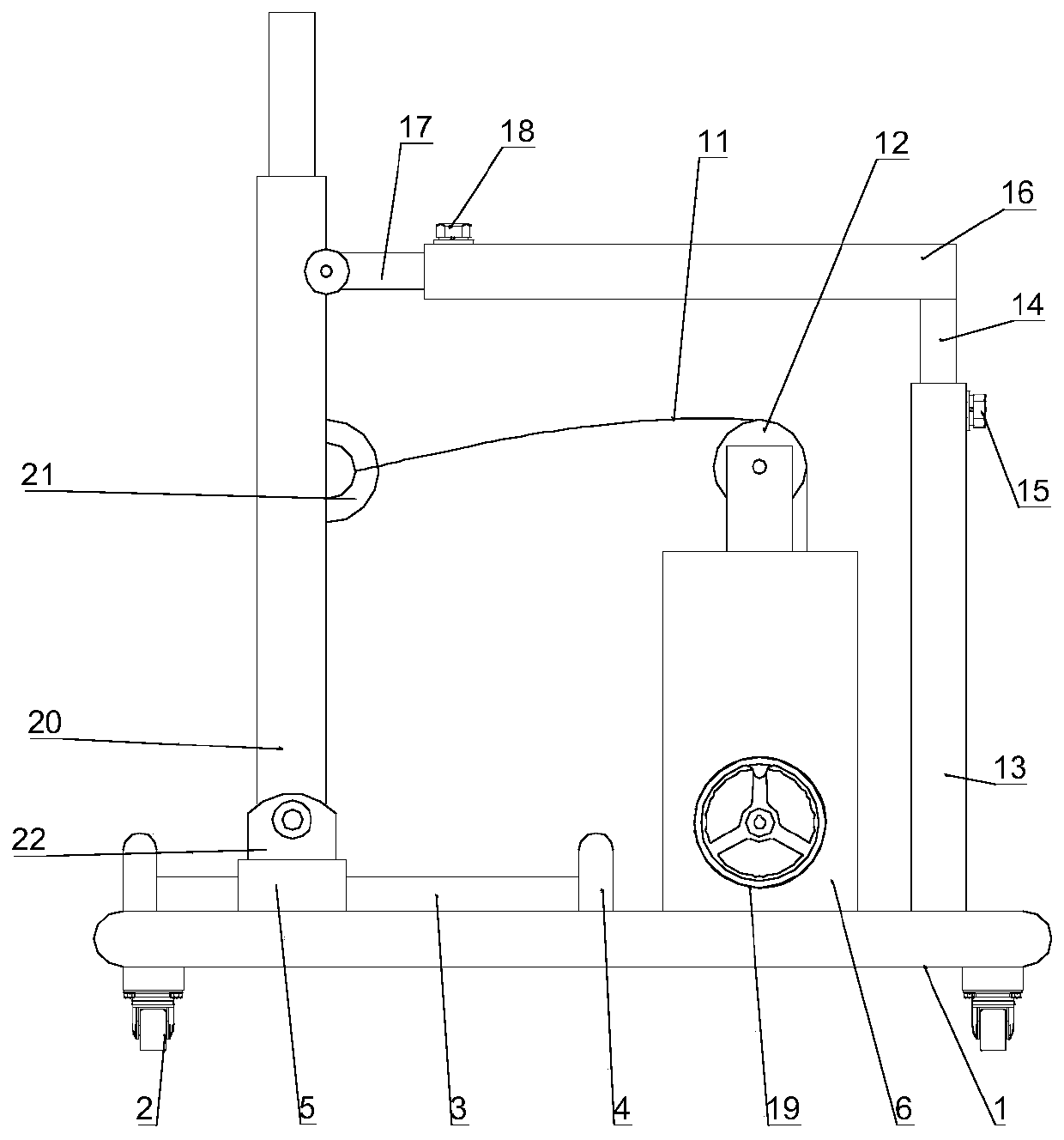
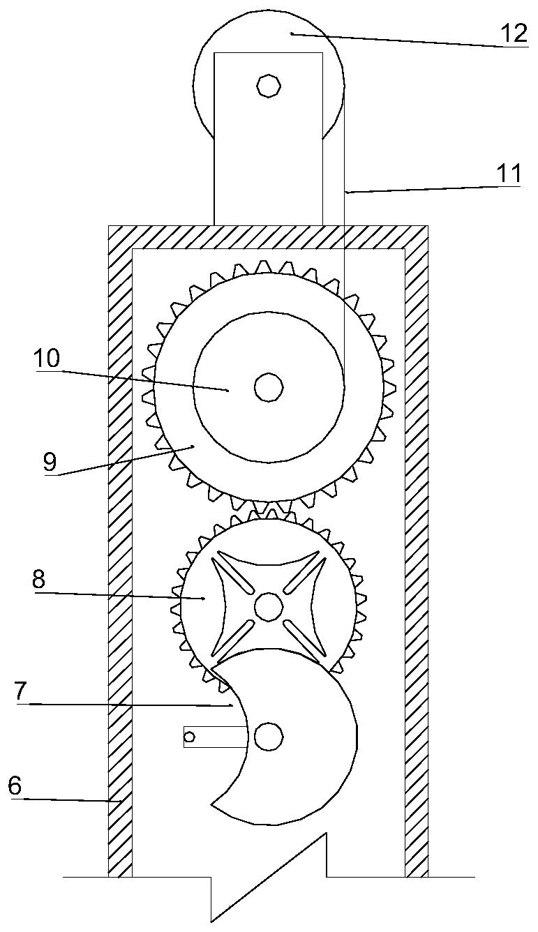
[0022] An adjustment device for engineering hydraulic supports, see figure 1 , including the support plate 1 and the self-locking universal roller 2 installed on the lower surface of the support plate 1, the upper surface of the support plate 1 is fixedly connected with a hollow box 6, a transmission device is installed in the hollow box 6, and the output end of the transmission device is fixedly connected There is a receiving roller 10, a connecting belt 11 is wound on the receiving roller 10, a rotating handle 19 is provided on the outer side of the support plate 1, a height adjusting device is fixedly connected to the support plate 1, and the top of the height adjusting device is fixedly connected with a displacement The adjusting device, the support plate 1 is fixedly connected with a slide rail 3, the two ends of the slide rail 3 are fixedly connected with a limit block 4, the slide rail 3 is slidably connected with a sliding sleeve 5, and the sliding sleeve 5 is fixedly c...
Embodiment 2
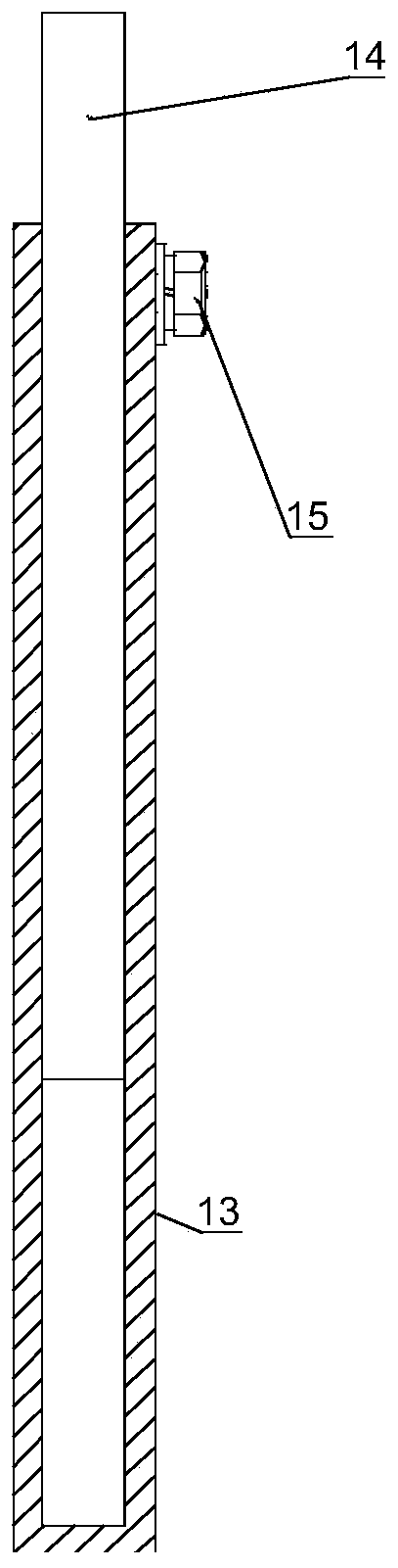
[0026] On the basis of Example 1, see Figure 2-3 , the hollow box 6 is fixedly connected with a guide roller 12, the connecting belt 11 passes through the guide roller 12, the height adjustment device includes a hollow sleeve body A13 that is fixedly connected with the support plate 1, and a free column passes through the hollow sleeve body A13. Body A14, a bolt A15 is installed on the hollow sleeve body A13, the displacement adjustment device includes a hollow sleeve body B16 fixedly connected with the top of the height adjustment device, the hollow sleeve body B16 passes through a free cylinder B17, and the hollow sleeve body B16 Bolt B18 is installed on it.
[0027] By loosening the bolts B18 and A15, the positions of the free cylinder B17 and the free cylinder A14 in the hollow sleeve body B16 and the hollow sleeve body A13 can be adjusted respectively. When the free cylinder B17 is adjusted to move left and right, the hydraulic support can be adjusted. 20 slides on the ...
PUM
 Abstract
Description
Claims
Application Information