Differential pressure limiting type six-way switch valve for conveying fluid

A six-way switching valve and fluid delivery technology, which is applied to multi-way valves, devices for pressure relief on the sealing surface, and lifting valves, etc., can solve the problem of unsatisfactory performance of valve parts, stuck, heavy workload, etc. problems, to avoid jamming and internal leakage, to avoid crushing the cam, and to improve the movement accuracy

Active Publication Date: 2019-01-11
九江七所精密机电科技有限公司
View PDF6 Cites 2 Cited by
  • Summary
  • Abstract
  • Description
  • Claims
  • Application Information

AI Technical Summary

Problems solved by technology

During the use process, the following disadvantages are concentrated: 1. When the main and standby interfaces are switched, the left and right linkage movement of the valve core is not smooth, the guide claw is deformed, the positioning is not accurate, and internal leakage is caused; 2. The valve parts cannot adapt to complex and complex valves. Changing on-site working conditions, the switching of low pressure difference is normal, and the switching torque increases sharply when switching of high pressure difference, and phenomena such as jamming and jamming often occur; 3. Once the valve core seal is damaged and replaced, the entire valve body needs to be removed for reassembly. Large amount, easy to cause secondary leakage
The above shortcomings lead to the unsatisfactory performance of the valve parts and the inability to realize convenient online switching

Method used


Image

  • Differential pressure limiting type six-way switch valve for conveying fluid
  • Differential pressure limiting type six-way switch valve for conveying fluid
  • Differential pressure limiting type six-way switch valve for conveying fluid

Examples


Embodiment Construction

[0024] The technical solutions of the present invention will be further described below in conjunction with the accompanying drawings and through specific implementation methods.

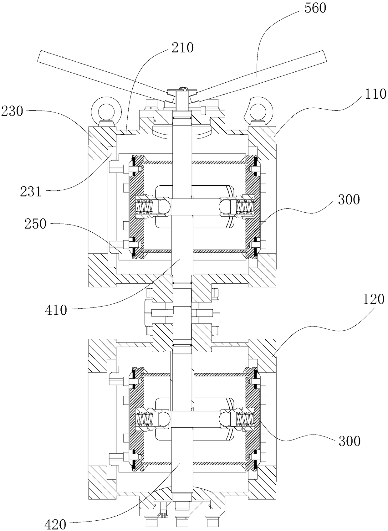
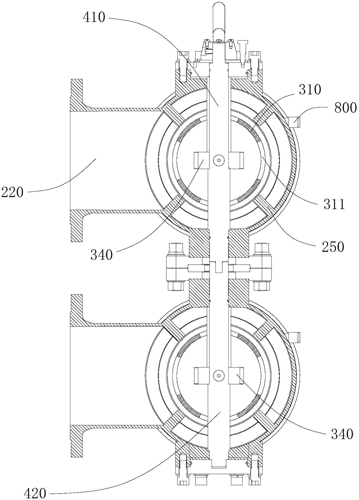
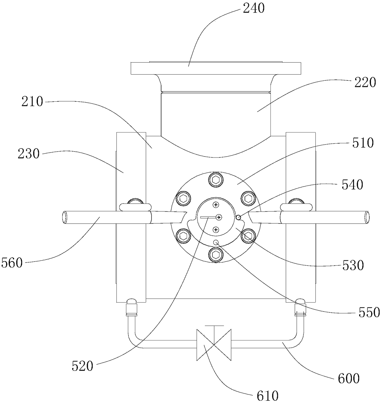
[0025] like Figure 1 to Figure 3 As shown, a specific embodiment of the present invention discloses a pressure-difference-limiting six-way switching valve for conveying fluids, including a first valve body 110 and a second valve body 120 connected to each other, and the first valve body 110 and the second valve body 120 are connected to each other. The second valve body 120 includes a pipe body 210 and a main pipe 220 fixed on the side wall of the pipe body 210, the main pipe 220 communicates with the pipe body 210, and both ends of the pipe body 210 are provided with Transition flange 230, the transition flange 230 and the two ends of the pipe body 210 are fixedly connected by bolts, the end of the main pipe 220 is fixedly provided with a connecting flange 240, the connection between the main pipe...


PUM


Abstract

The invention provides a differential pressure limiting type six-way switch valve for conveying fluid. The differential pressure limiting type six-way switch valve comprises a first valve body and a second valve body which are mutually connected. The first valve body and the second valve body each comprise a pipe body and a header pipe, wherein the two ends of the pipe body are provided with transition flanges, the flow passage junction of the header pipe and the pipe body is provided with a linkage valve element, the two end faces of the linkage valve element are provided with sealing rings,multiple guide sliding rails are fixedly arranged on the inner wall of the pipe body, the side walls, close to the axial line of the pipe body, of the guide sliding rails are in sliding abutting connection with the side wall of a valve plate, a cam is arranged in the linkage valve element, the two ends inside the linkage element are fixedly provided with elastic supporting parts, the two elastic supporting parts located in the same linkage valve element make abutting contact with the cam so as to build rolling connection, a first rotating shaft penetrating through the linkage valve element isarranged in the first valve body, a second rotating shaft penetrates through the linkage valve element is arranged in the second valve body, and the second rotating shaft is connected with the first rotating shaft. The differential pressure limiting type six-way switch valve is novel, optimal and reasonable in structure, and has the advantages that moving is smooth, sealing is reliable, and maintenance is convenient.

Description

technical field [0001] The invention relates to the field of switching valves, and more specifically, to a pressure-difference-limiting six-way switching valve for conveying fluids. Background technique [0002] The existing six-way switching valves in the market basically adopt the line contact friction between the cam and the spool to make the spool move to complete the switching. When the spool moves, the main and backup interfaces are respectively provided with guide claws, and the spool seal is installed from the inside of the valve body. During the use process, the following disadvantages are concentrated: 1. When the main and standby interfaces are switched, the left and right linkage movement of the valve core is not smooth, the guide claw is deformed, the positioning is inaccurate, and internal leakage is caused; 2. The valve parts cannot adapt to complex and diverse Changing on-site working conditions, low pressure differential switching is normal, switching torque...

Claims


Application Information

Patent Timeline
Patent Type & Authority Applications(China)
IPC IPC(8): F16K11/044F16K1/44F16K1/46F16K39/02F16K27/02F16K31/524
CPCF16K1/44F16K1/46F16K11/044F16K27/0263F16K31/52416F16K39/02
Inventor 孙梦楠宋显国胡协桂王佳张程狄俊平佘婷婷武永前
Owner 九江七所精密机电科技有限公司
Why Eureka
Try Eureka