Unintermittent phase change energy storage and heat exchange system

A phase change energy storage and heat exchange system technology, applied in indirect heat exchangers, heat storage equipment, heat exchanger types, etc., can solve the inconsistency between heat time and space, reduce heat exchange efficiency and service life of heat exchangers , time and space energy supply conflicts, etc., to achieve the effect of flexible and reasonable allocation of time and space, low cost of materials and structures, and simple and compact structure

Pending Publication Date: 2019-01-11
UNIV OF SHANGHAI FOR SCI & TECH
View PDF5 Cites 5 Cited by
  • Summary
  • Abstract
  • Description
  • Claims
  • Application Information

AI Technical Summary

Problems solved by technology

[0002] Traditional heat exchangers cannot store energy, but can only exchange heat, and there is a time and space inconsistency in the supply and consumption of heat. There is not enough heat when it is needed, and there is a lot of heat when it is not needed. The heat is lost to the cold fluid, resulting in a serious waste of resources
In addition, the cold and hot fluids in the existing energy storage system cannot work at the same time, the energy cannot be supplied in time, and there is an energy supply conflict in time and space; at the same time, the fluid is easy to condense and deteriorates the heat transfer, reducing the heat transfer efficiency and service life of the heat exchanger , which seriously affects energy utilization

Method used


Image

  • Unintermittent phase change energy storage and heat exchange system
  • Unintermittent phase change energy storage and heat exchange system
  • Unintermittent phase change energy storage and heat exchange system

Examples


Embodiment Construction

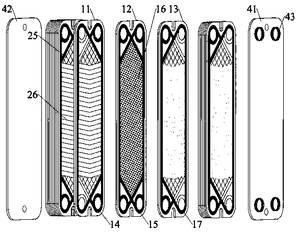
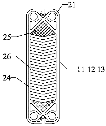
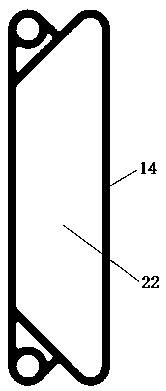
[0017] Example Figure 1 to Figure 4 As shown, the uninterrupted phase change energy storage and heat exchange system of the present invention includes several sequentially stacked phase change energy storage and heat exchange units, and the phase change energy storage and heat exchange units include a first plate heat exchange fin 11, a second Plate heat exchange fins 12, third plate heat exchange fins 13, first semi-enclosed seal ring 14, second semi-enclosed seal ring 17, fully enclosed seal ring 15 and phase change material 16, the first plate heat exchange fin 11 1. The second plate heat exchange fin 12 and the third plate heat exchange fin 13 are respectively arranged in parallel at intervals, and the four corners are respectively provided with through holes 21, and the first semi-closed sealing ring 14 is arranged on the first plate heat exchange fin 11 Between the second plate heat exchange fin 12 and the upper and lower through holes on one side of the first plate hea...


PUM


Abstract

The invention discloses an unintermittent phase change energy storage and heat exchange system. The system comprises a plurality of phase change energy storage and heat exchange units. Each phase change energy storage and heat exchange unit comprises a first heat exchange plate, a second heat exchange plate, a third heat exchange plate, two semi-closed sealing rings, a totally-closed sealing ringand a phase change material. The three heat exchange plates are arranged at intervals, and the four corners of each heat exchange plate are provided with through holes. The first semi-closed sealing ring is arranged between the first heat exchange plate and the second heat exchange plate, so that the upper and lower through holes on one side communicate directly, and the upper and lower through holes on the other side communicate with an enclosed space. The totally-closed sealing ring is arranged between the second heat exchange plate and the third heat exchange plate, so that the through holes at the four corners directly communicate, and a totally-closed space is formed between the second heat exchange plate and the third heat exchange plate. The phase change material is arranged in thetotally-closed space. The second semi-closed sealing ring is reversely arranged on the other side of the third heat exchange plate. The three heat exchange plates constitute a cold fluid channel and ahot fluid channel through the semi-closed sealing rings and the totally-closed sealing ring. The unintermittent phase change energy storage and heat exchange system increases the heat exchange coefficient and realizes fast response to heat storage and release so that energy can be distributed flexibly and reasonably.

Description

technical field [0001] The invention relates to an uninterrupted phase change energy storage and heat exchange system. Background technique [0002] Traditional heat exchangers cannot store energy, but can only exchange heat, and there is a time and space inconsistency in the supply and consumption of heat. There is not enough heat when it is needed, and there is a lot of heat when it is not needed. The heat is lost to the cold fluid, resulting in a serious waste of resources. In addition, the cold and hot fluids in the existing energy storage system cannot work at the same time, the energy cannot be supplied in time, and there is an energy supply conflict in time and space; at the same time, the fluid is easy to condense and deteriorates the heat transfer, reducing the heat transfer efficiency and service life of the heat exchanger , seriously affecting energy utilization. Contents of the invention [0003] The technical problem to be solved by the present invention is ...

Claims


Application Information

Patent Timeline
Patent Type & Authority Applications(China)
IPC IPC(8): F28D20/02F28D9/00
CPCF28D9/00F28D20/02Y02E60/14
Inventor 胡卓焕李瑞高润毅彭威沈若鸿
Owner UNIV OF SHANGHAI FOR SCI & TECH
Why Eureka
Try Eureka