Low-friction high-damping pendulum type automatic balancing device for rotary machine

A rotating machinery, automatic balancing technology, applied in static/dynamic balance testing, measuring device, machine/structural component testing, etc., can solve the problem of determining parameters affecting the rotational speed, reducing the balance of rotating machinery, increasing the amplitude of the vibrator system, etc. , to achieve the effect of improving subcritical parameters, avoiding resistance, and increasing low speed values

Active Publication Date: 2019-01-11
太仓戴萌兔服饰有限公司
View PDF5 Cites 3 Cited by
  • Summary
  • Abstract
  • Description
  • Claims
  • Application Information

AI Technical Summary

Problems solved by technology

[0004] The purpose of the present invention is to provide a pendulum-type automatic balancing device with low friction and high shock absorption for rotating machinery, so as to solve the problems of the existing pendulum-type automatic balancing device for rotating machinery proposed in the background technology at low speed or subcritical The degree of eccentricity is aggravated in the state, the amplitude of the vibrator system is increased, and the balance of the rotating machine is reduced, so the scope of use of the pendulum-type automatic balancing device is limited, and the pendulum in the pendulum-type automatic balancing device is in motion. , the resistance encountered will also affect the speed and reduce the problem of the decisive parameter of the subcritical

Method used


Image

  • Low-friction high-damping pendulum type automatic balancing device for rotary machine
  • Low-friction high-damping pendulum type automatic balancing device for rotary machine
  • Low-friction high-damping pendulum type automatic balancing device for rotary machine

Examples


Embodiment Construction

[0029] The technical solutions in the embodiments of the present invention will be clearly and completely described below in conjunction with the accompanying drawings in the embodiments of the present invention. Obviously, the described embodiments are only some of the embodiments of the present invention, not all of them. Based on The embodiments of the present invention and all other embodiments obtained by persons of ordinary skill in the art without making creative efforts belong to the protection scope of the present invention.

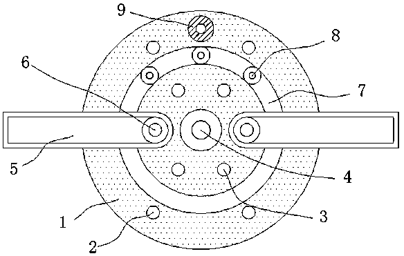
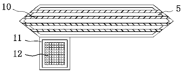
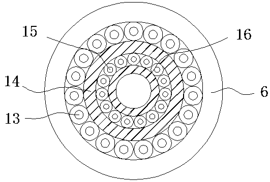
[0030] see Figure 1-6 , the present invention provides a technical solution: a pendulum-type automatic balancing device with low friction and high shock absorption for rotating machinery, including a turntable 1, a first mounting hole 2, a second mounting hole 3, a first rotating shaft 4, a pendulum 5. The second rotating shaft 6, the chute 7, the first steel ball 8, the eccentric mass cylinder 9, the through groove 10, the weighted frame 11, t...


PUM


Abstract

The invention relates to a low-friction high-damping pendulum type automatic balancing device for a rotary machine, comprising a rotary disc, and a weighting frame. A first mounting hole is arranged in the outer layer of the front face of the rotary disc. A second mounting hole is arranged in the middle layer of the front face of the rotary disc. A first rotary shaft is mounted in the middle of the front face of the rotary disc. The invention has the advantages that the first mounting hole and the second mounting hole are respectively arranged on the outer side and the middle portion of the front face of the rotary disc, so that the mounting quantity of the pendulums on the upper end of the rotary disc can be increased, the mounting can be performed according to the balance requirement ofthe rotary machine; the mounting position of the pendulum on the rotary disc, i.e., the distance of the pendulum and the center point of the rotary disc can be changed; mounting can be selected according to the specification of the rotary machine, so as to prevent the distance of the pendulum to the center point of the rotary disc from being far away, thereby preventing the collision between the outer side of the pendulum and the rotary machine; the pendulum can also be mounted to the first mounting hole without colliding, so that the distance to the center point of the pendulum is increased,and the farther the distance the less the produced amplitude.

Description

technical field [0001] The invention relates to the technical field of a pendulum-type automatic balancing device for rotating machines, in particular to a pendulum-type automatic balancing device for rotating machines with low friction and high shock absorption. Background technique [0002] During the movement of the rotating machinery, it needs to rely on the automatic balancing device to maintain its balanced movement. The pendulum type automatic balancing device is commonly used in the rotating machinery. The pendulum type automatic balancing device uses the automatic centering principle of the rotor. The hammer-type automatic balancing device can balance well at high speed. [0003] The existing pendulum-type automatic balancing device for rotating machinery intensifies the degree of eccentricity at low speed or in a subcritical state, which increases the amplitude of the vibrator system and reduces the balance of the rotating machinery, so the pendulum-type automatic ...

Claims


Application Information

Patent Timeline
Patent Type & Authority Applications(China)
IPC IPC(8): G01M1/32
CPCG01M1/32
Inventor 李川龙建宇
Owner 太仓戴萌兔服饰有限公司
Why Eureka
Try Eureka