
Unmanned aerial vehicle for high-altitude air quality detection

A high-altitude air and air quality technology, applied in the field of unmanned aerial vehicles, can solve the problems of detection box pollution, affecting detection results, inaccurate air quality detection results, etc., to achieve the effect of improving accuracy, improving work efficiency, and ensuring accuracy

Inactive Publication Date: 2019-01-11
易蕾
View PDF12 Cites 10 Cited by
  • Summary
  • Abstract
  • Description
  • Claims
  • Application Information

AI Technical Summary

Problems solved by technology

[0003] An existing UAV used for high-altitude air quality detection has some disadvantages in detection. When the UAV is in high-altitude air quality detection, it needs to detect multiple sets of data. When the air enters the detection box for detection, the detection The final air will still remain in the test box, causing the next set of air quality test results to be inaccurate. When operating at high altitude, there may be other impurities in the air, which will easily cause the inside of the test box to be polluted and affect the test results.

Method used


Image

  • Unmanned aerial vehicle for high-altitude air quality detection
  • Unmanned aerial vehicle for high-altitude air quality detection
  • Unmanned aerial vehicle for high-altitude air quality detection

Examples


Embodiment Construction

[0023] The following will clearly and completely describe the technical solutions in the embodiments of the present invention with reference to the accompanying drawings in the embodiments of the present invention. Obviously, the described embodiments are only some, not all, embodiments of the present invention.

[0024] In describing the present invention, it should be understood that the terms "upper", "lower", "front", "rear", "left", "right", "top", "bottom", "inner", " The orientation or positional relationship indicated by "outside", etc. is based on the orientation or positional relationship shown in the drawings, and is only for the convenience of describing the present invention and simplifying the description, rather than indicating or implying that the referred device or element must have a specific orientation, so as to Specific orientation configurations and operations, therefore, are not to be construed as limitations on the invention.

[0025] refer to Figure ...


PUM


Abstract

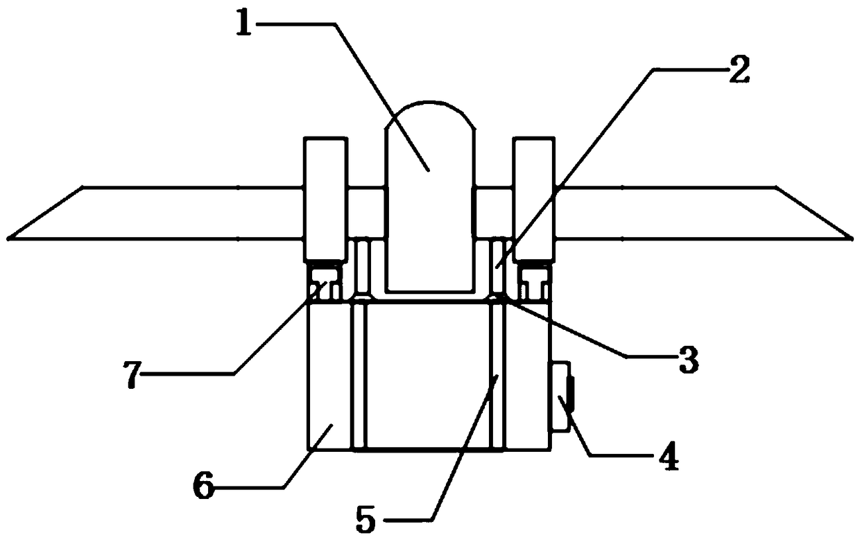
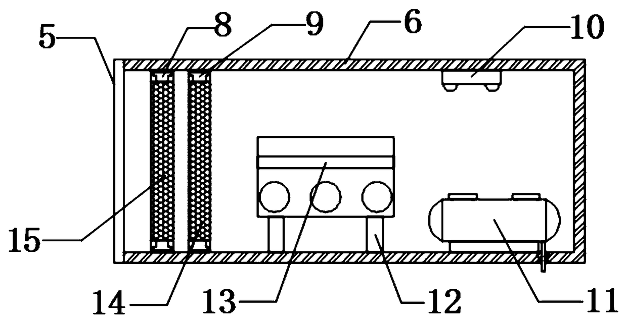
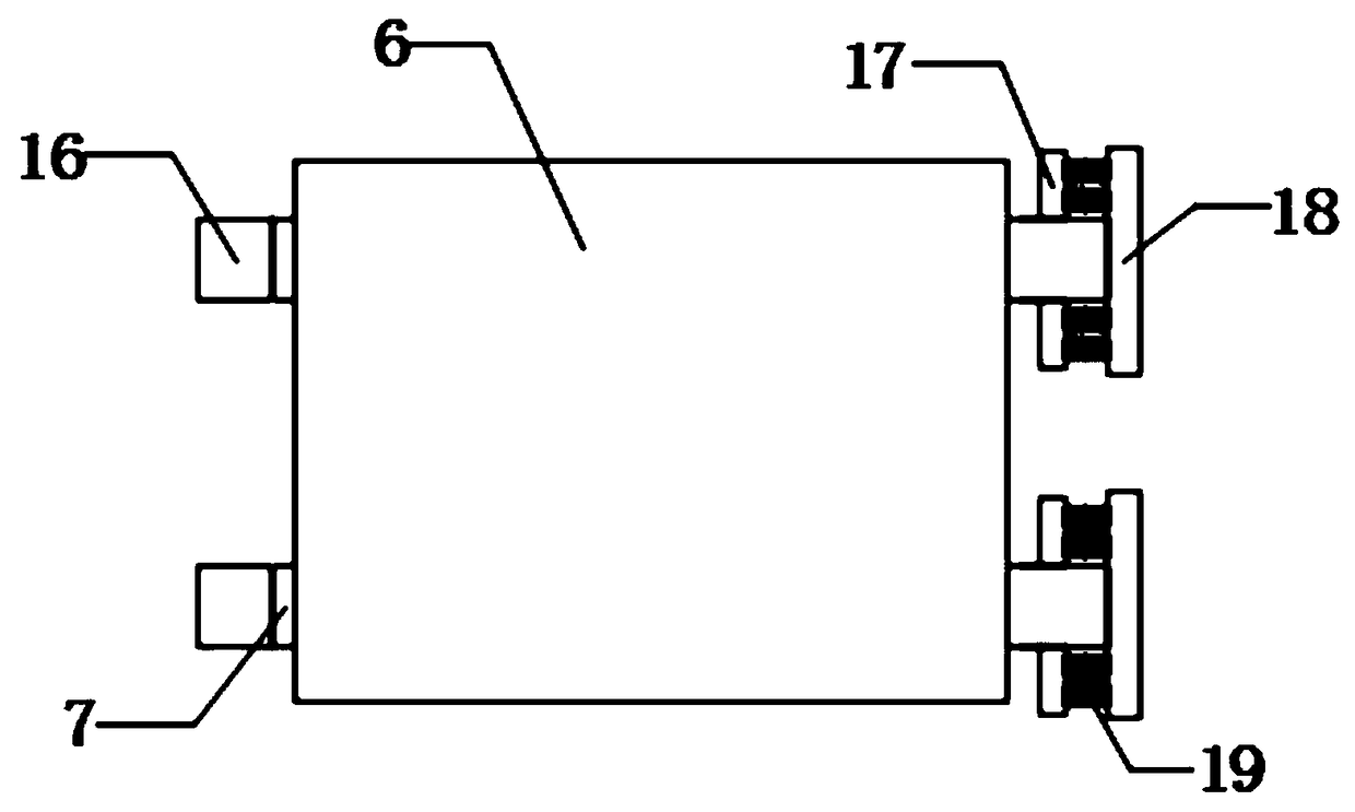
The invention discloses an unmanned aerial vehicle for high-altitude air quality detection. The unmanned aerial vehicle comprises an unmanned aerial vehicle body; the outer walls at the bottom of thetwo ends of the unmanned aerial vehicle body are each provided with a first sliding groove; furthermore, a detection box is glidingly connected to the inner walls of the two first sliding grooves; theouter walls at one ends of the two first sliding grooves are each welded with a fixed block; furthermore, the outer walls at two sides of the other ends of the two first sliding grooves are each provided with a limiting block; the outer walls at one sides of the four limiting blocks are each provided with two spring rods; the outer walls at the other ends of the spring rods are each provided witha limiting plate; the outer wall of the bottom of the unmanned aerial vehicle body positioned at the inner sides of the two first sliding grooves is provided with two fixed rods; and furthermore, theouter walls at the bottoms of the two fixed rods are each provided with a suction cup. According to the unmanned aerial vehicle in the invention, a first filter net layer and a second filter net layer are arranged; therefore, some impurities in high altitude cannot enter the detection box; the accuracy of a detection result is ensured; the first filter net layer and the second filter net layer are glidingly connected to the inner walls of the second sliding groove and the third sliding groove; therefore, the filter net layer is convenient to replace; and the working efficiency is increased.

Description

technical field [0001] The invention relates to the technical field of unmanned aerial vehicles, in particular to an unmanned aerial vehicle used for high-altitude air quality detection. Background technique [0002] With the improvement of UAV technology, UAVs can be used in many aspects. For example, UAVs are used in agriculture for pesticide spraying, and UAVs are also required for high-altitude air quality inspections. [0003] An existing UAV used for high-altitude air quality detection has some disadvantages in detection. When the UAV is in high-altitude air quality detection, it needs to detect multiple sets of data. When the air enters the detection box for detection, the detection The remaining air will still remain in the test box, causing the next set of air quality test results to be inaccurate. When operating at high altitude, there may be other impurities in the air, which will easily cause the inside of the test box to be polluted and affect the test results. ...

Claims


Application Information

Patent Timeline
IPC IPC(8): G01N1/24G01N1/26G01N33/00
CPCG01N1/24G01N1/26G01N33/0004
Inventor 易蕾袁毅毛敏
Owner 易蕾
Learn More