Supermode microstructure optical fiber for transmitting orbital angular momentum

A technology of micro-structured optical fibers and transmission tracks, applied in the directions of multi-layer core/clad optical fibers, clad optical fibers, light guides, etc. problems such as the difficulty of solving the problem, so as to achieve the effect of low limit loss and large effective mode area.

Active Publication Date: 2019-01-11
SHENZHEN SDG INFORMATION CO LTD
View PDF6 Cites 9 Cited by
  • Summary
  • Abstract
  • Description
  • Claims
  • Application Information

AI Technical Summary

Problems solved by technology

For example, the ring-core photonic crystal fiber designed in the prior art supports 26 orbital angular momentum modes, and uses 4 layers of air hole cladding to reduce the limiting loss. The maximum limiting loss at 1.55um is 0.003db / m, but due to the ring core area Due to the width limitation, it is impossible to flexibly increase the orbital angular momentum mode, that is, when the width of the ring core area increases, the effective refractive index difference between the vector modes decreases, and it is easy to form a linear polarization mode, which affects the stable transmission of the orbital angular momentum. At the same time, the ring core The increase of the area width is easy to generate radial high-order mode, which increases the difficulty of demultiplexing

Method used


Image

  • Supermode microstructure optical fiber for transmitting orbital angular momentum
  • Supermode microstructure optical fiber for transmitting orbital angular momentum
  • Supermode microstructure optical fiber for transmitting orbital angular momentum

Examples


Embodiment 1

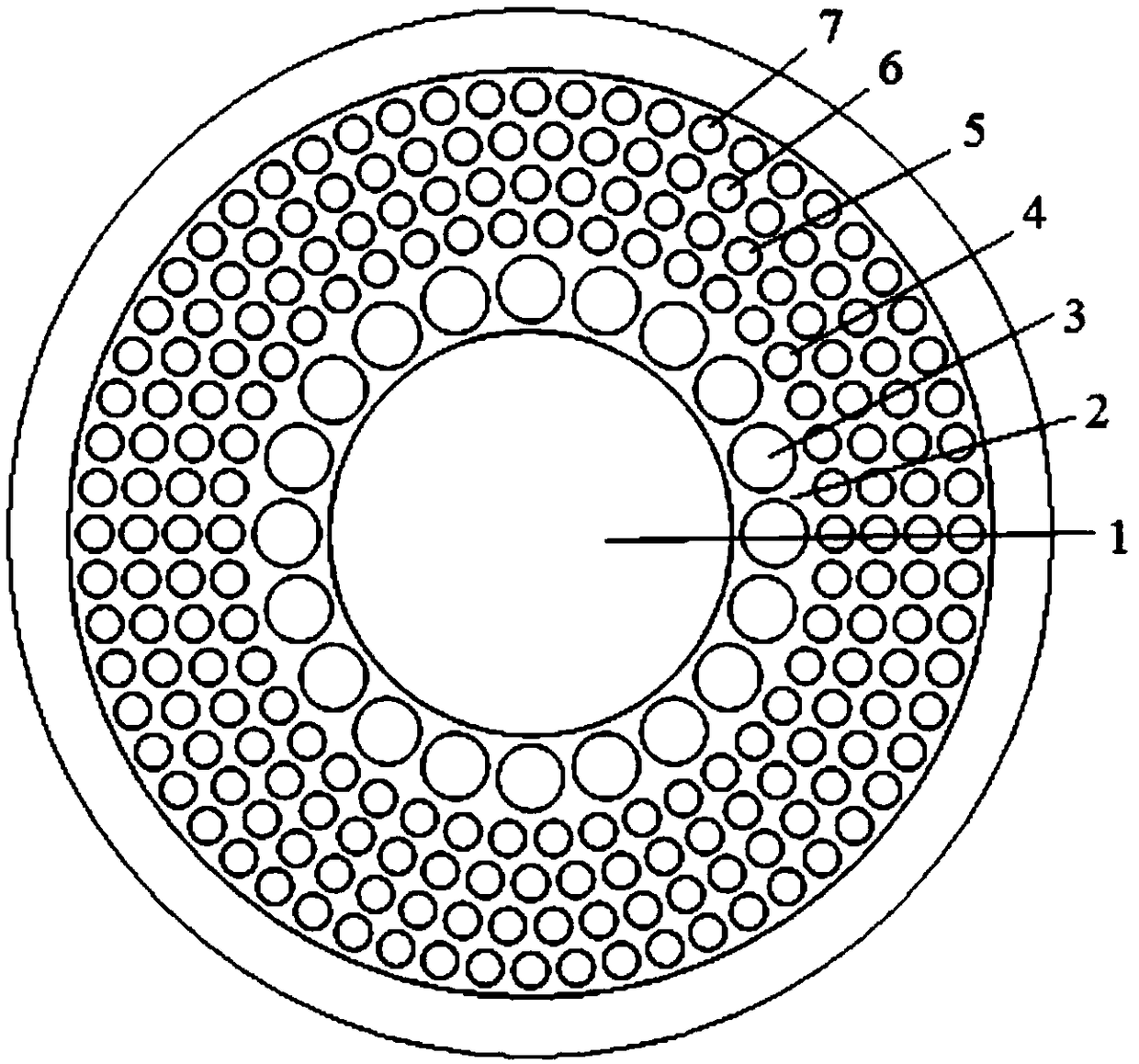
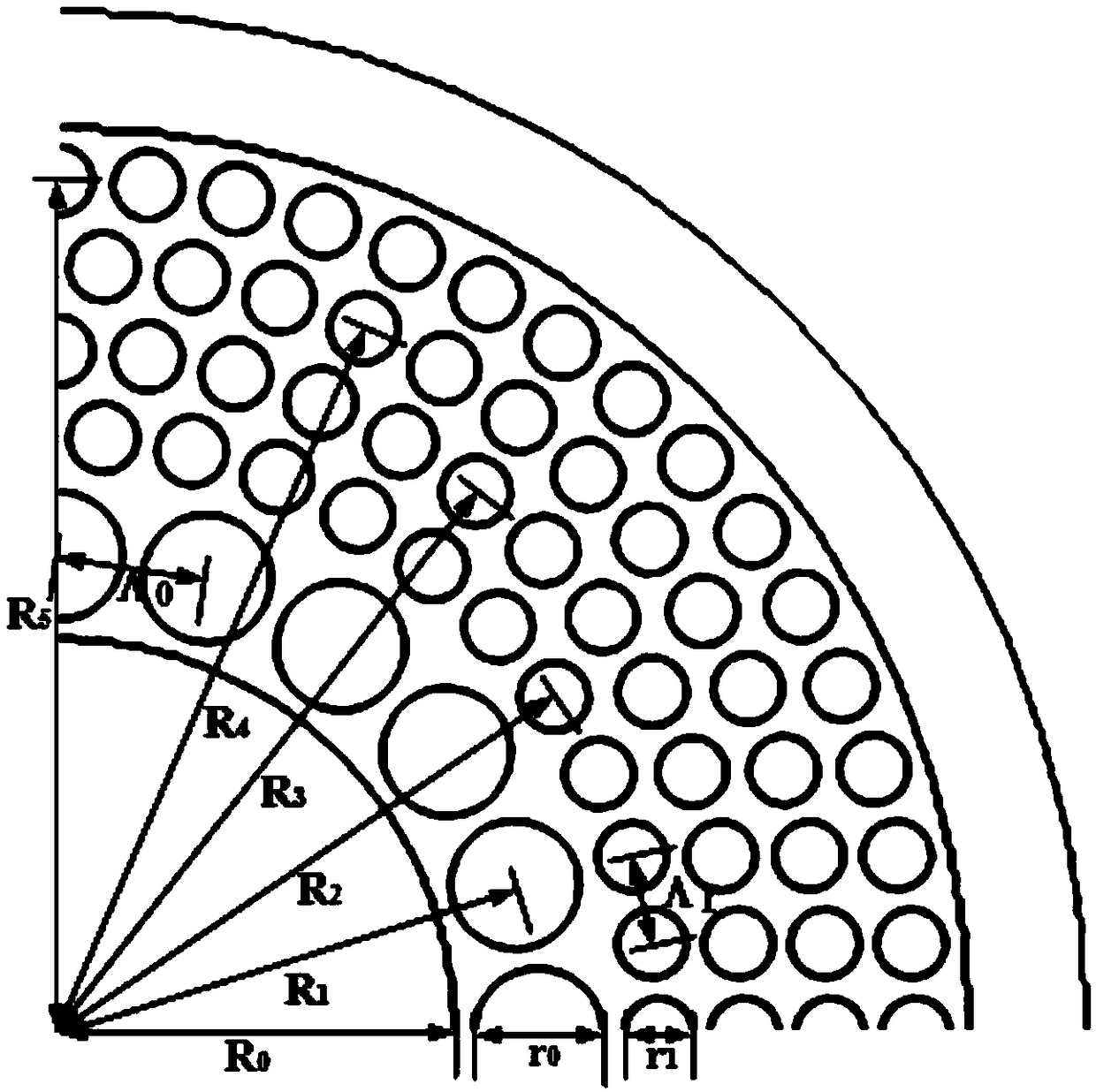
[0042] Embodiment 1: The radius R of the central air hole 1 0 =18.4um; the substrate 2 is pure silica glass; the refractive index of the annular array core region 3 doped quartz column is n at the wavelength of 1.55um 1 = 1.457, radius r 0 =2.98um, the distance to the fiber center is R 1 =22.2um, the distance between two adjacent doped quartz columns Λ 0 =6.95um; the air hole radius r of the first cladding layer 4, the second cladding layer 5, the third cladding layer 6 and the fourth cladding layer 7 in the fiber cladding area 1 =1.58um, the center distance R of 4 pairs of optical fibers in the first cladding layer 2 =27.8um, distance R between 5 pairs of optical fibers in the second cladding layer 3 =31.8um, distance R between 6 pairs of optical fibers in the third cladding layer 4 =35.8um, the fourth cladding 7 pairs of fiber center distance R 5 = 39.8um. The spacing Λ of adjacent air holes in the first cladding layer 4, the second cladding layer 5, the third claddin...

Embodiment 2

[0043] Embodiment 2: The radius R of the central air hole 1 0 =18.6um; the substrate 2 is pure silica glass; the refractive index of the annular array core region 3 doped quartz column is n at the wavelength of 1.55um 1 = 1.463, radius r 0 =3.02um, the distance to the fiber center is R 1 =22.6um, the distance between two adjacent doped quartz columns Λ 0 =7.07um; the air hole radius r of the first cladding layer 4, the second cladding layer 5, the third cladding layer 6 and the fourth cladding layer 7 of the optical fiber cladding area 1 =1.62um, the center distance R of 4 pairs of optical fibers in the first cladding layer 2 =28.2um, distance R between 5 pairs of optical fibers in the second cladding layer 3 =32.2um, distance R between 6 pairs of optical fibers in the third cladding layer 4 =36.2um, the fourth cladding 7 pairs of fiber center distance R 5 = 40.2um. The spacing Λ of adjacent air holes in the first cladding layer 4, the second cladding layer 5, the third...


PUM


Abstract

The invention discloses a supermode microstructure optical fiber for transmitting orbital angular momentum. The supermode microstructure optical fiber comprises: a central air hole, a substrate material, a ring array fiber core area and a cladding layer area, wherein the circle center of the central air hole is located at the center of the optical fiber, the ring array fiber core area comprises anoptical fiber substrate and a plurality of doped quartz columns uniformly arranged along the central air hole, the cladding layer area is located on the outer side of the ring array fiber core area and share the circle center with the central air hole, the cladding layer area is a circular microstructure cladding layer composed of a first cladding layer, a second cladding layer, a third claddinglayer and a fourth cladding layer, wherein the first cladding layer, the second cladding layer, the third cladding layer and the fourth cladding layer are respectively composed of 42, 48, 54 and 60 circular air holes which are annularly and uniformly arranged. The working wavelength range of the optical fiber disclosed by the invention is 1.0 to 1.8 um, 60 orbital angular momentum modes can be supported within the working wavelength range, the limiting loss of the modes is low, the dispersion is small, and the effective mode area is large.

Description

technical field [0001] The invention relates to the field of optical fiber communication, in particular to a supermode microstructure optical fiber for transmitting orbital angular momentum. Background technique [0002] As the carrier of optical signal transmission, optical fiber has become the most important part of optical communication system. Most of the existing optical fiber communication networks use multiplexing technologies such as wavelength division multiplexing and time division multiplexing to expand capacity. However, with the advancement of modern society and the vigorous development of the information age, people's requirements for network bandwidth are getting higher and higher, and the capacity of optical fiber communication systems based on technologies such as wavelength division multiplexing is getting closer and closer to Shannon's limit. In order to expand the communication capacity, people have applied space division multiplexing technology to optic...

Claims


Application Information

Patent Timeline
Patent Type & Authority Applications(China)
IPC IPC(8): G02B6/02G02B6/032G02B6/036
CPCG02B6/02314G02B6/032G02B6/03661
Inventor 王伟徐海东林天旭朱维震董婷婷卿源杨琪豪李正然周凡迪
Owner SHENZHEN SDG INFORMATION CO LTD
Why Eureka
Try Eureka