
Optical fiber debugging method of localized protection device and localized protection device

A technology of protection device and debugging method, which is applied in the direction of optical fiber transmission, data exchange through path configuration, transmission system, etc., can solve problems such as the inability to realize bottom-level hardware debugging, and facilitate detection and debugging, improve anti-interference performance, increase bandwidth and reliability effect

Inactive Publication Date: 2019-01-11
STATE GRID CORP OF CHINA +3
View PDF9 Cites 0 Cited by
  • Summary
  • Abstract
  • Description
  • Claims
  • Application Information

AI Technical Summary

Problems solved by technology

However, in order to monitor the working status of the underlying hardware of the local protection device, it is necessary to obtain the serial port debugging information of the local protection device, which is convenient for locating and diagnosing field faults. For the local protection device without a dedicated debugging serial port, it is impossible to realize the underlying hardware Debugging of working status

Method used


Image

  • Optical fiber debugging method of localized protection device and localized protection device
  • Optical fiber debugging method of localized protection device and localized protection device
  • Optical fiber debugging method of localized protection device and localized protection device

Examples


Embodiment Construction

[0042] Various exemplary embodiments, features, and aspects of the present disclosure will be described in detail below with reference to the accompanying drawings. The same reference numbers in the figures indicate functionally identical or similar elements. While various aspects of the embodiments are shown in drawings, the drawings are not necessarily drawn to scale unless specifically indicated.

[0043] The word "exemplary" is used exclusively herein to mean "serving as an example, embodiment, or illustration." Any embodiment described herein as "exemplary" is not necessarily to be construed as superior or better than other embodiments.

[0044] In addition, in order to better illustrate the present disclosure, numerous specific details are given in the following specific implementation manners. It will be understood by those skilled in the art that the present disclosure may be practiced without some of the specific details. In some instances, methods, means, componen...


PUM


Abstract

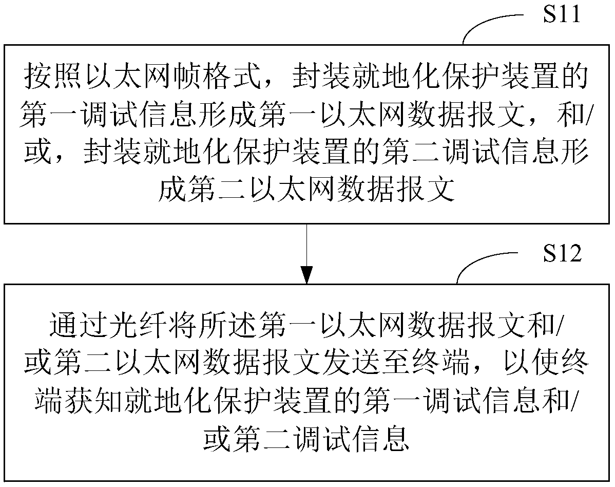
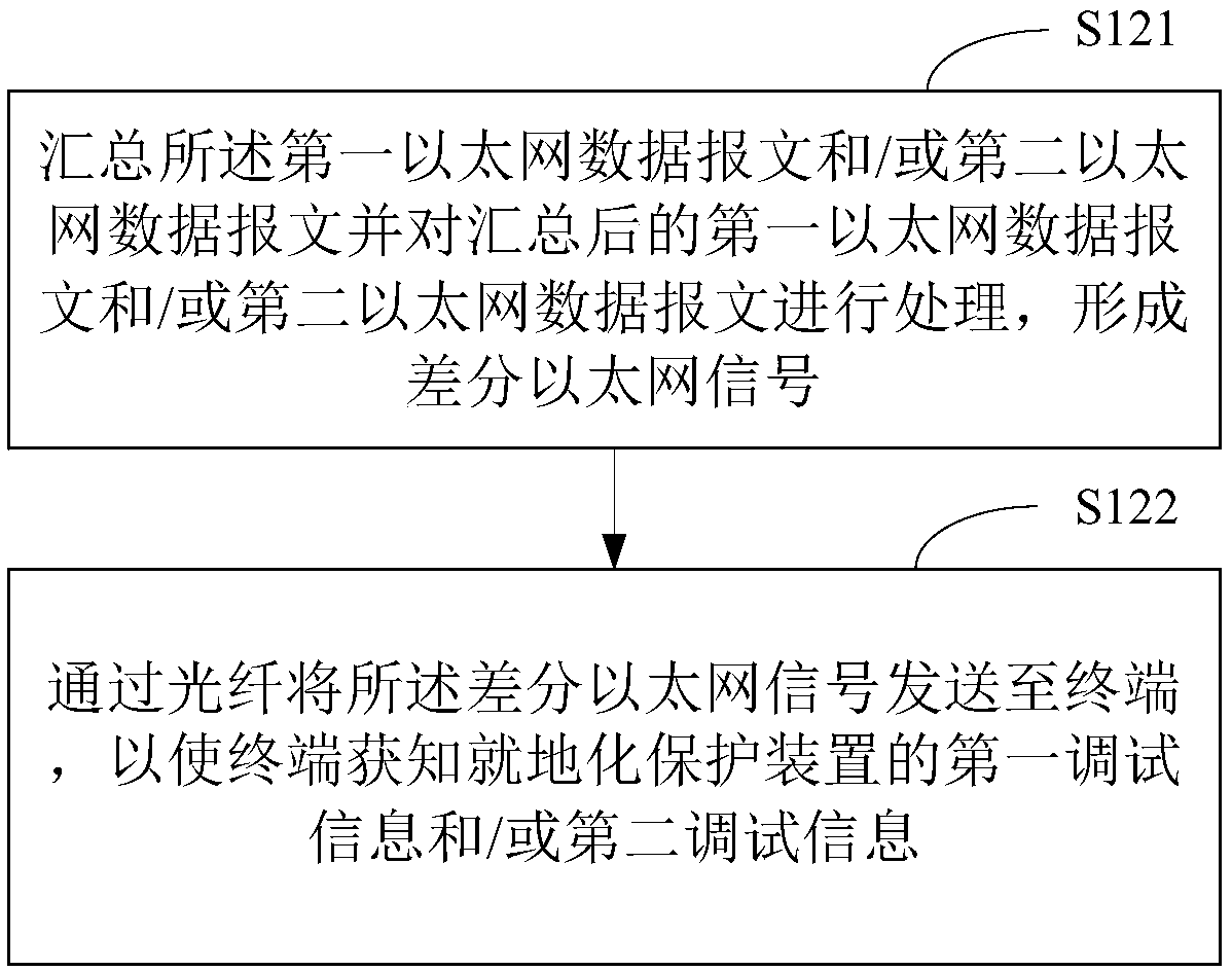
The invention relates to an optical fiber debugging method of a localized protection device and a localized protection device. The method comprises: according to an Ethernet frame format, encapsulating the first debugging information of the localized protection device to form a first Ethernet data message; and / or encapsulating the second debugging information of the localized protection device toform a second Ethernet data message; sending the first Ethernet data message and / or the second Ethernet data message to the terminal through the optical fiber so that the terminal can obtain the firstdebugging information and / or the second debugging information of the localized protection device. In accordance with the Ethernet frame format, the serial port debugging information of the protectionCPU and / or the serial port debugging information of the management CPU of the localized protection device are / is encapsulated and are sent to the terminal through the optical fiber to achieve the purpose of monitoring the debugging information of the serial port of the localized protection device without the debugging serial port externally, and the optical fiber sending mode improves the bandwidth and reliability of the debugging interface.

Description

technical field [0001] The disclosure relates to the field of power equipment debugging, and in particular to an optical fiber debugging method of an in-situ protection device and the in-situ protection device. Background technique [0002] The in-situ protection device is a protection device installed directly in the switchyard or integrated with primary equipment. It is characterized by high protection level, no LCD screen and operation panel, and external connection with aviation plug, which can realize plug and play. [0003] Due to the harsh installation environment of the in-situ protection device, in order to improve the protection level and anti-interference ability of the in-situ protection device, the volume of the in-situ protection device should be reduced as much as possible during design, and the number and types of external interfaces should be reduced, especially for substations. Due to the harsh electromagnetic environment around the equipment, the external ...

Claims


Application Information

Patent Timeline
IPC IPC(8): G06F11/30H04B10/25H04B10/66H04L12/28
CPCG06F11/3041H04B10/25H04B10/66H04L12/28H04B10/25891
Inventor 王德林刘宇裘愉涛盛海华方喻冬徐灵江吴佳毅耿烺黄志华王小仲唐明姚建锋刘莹徐刚陈秋荣徐万方胡炯蒋新成
Owner STATE GRID CORP OF CHINA
Learn More