Air-cooled liquid-cooled combined thermally superconducting plate radiator

A technology of thermal superconductivity and heat sink, applied in the field of heat transfer, can solve the problems that aluminum heat sinks cannot meet the heat dissipation requirements of high heat flux density and high power modules, and achieve long-term stable operation, improved heat dissipation capacity, and high heat conduction efficiency Effect

Pending Publication Date: 2019-01-11
ZHEJIANG JIAXI TECH CO LTD
View PDF0 Cites 5 Cited by
  • Summary
  • Abstract
  • Description
  • Claims
  • Application Information

AI Technical Summary

Problems solved by technology

[0003] In view of the shortcomings of the prior art described above, the purpose of the present invention is to provide an air-cooled liquid-cooled combined thermal superconducting plate radiator, which is used to solve the problem that the aluminum radiator in the prior art cannot meet the requirements of high heat flux density and high power. The cooling requirements of the modules

Method used


Image

  • Air-cooled liquid-cooled combined thermally superconducting plate radiator
  • Air-cooled liquid-cooled combined thermally superconducting plate radiator
  • Air-cooled liquid-cooled combined thermally superconducting plate radiator

Examples


Embodiment 1

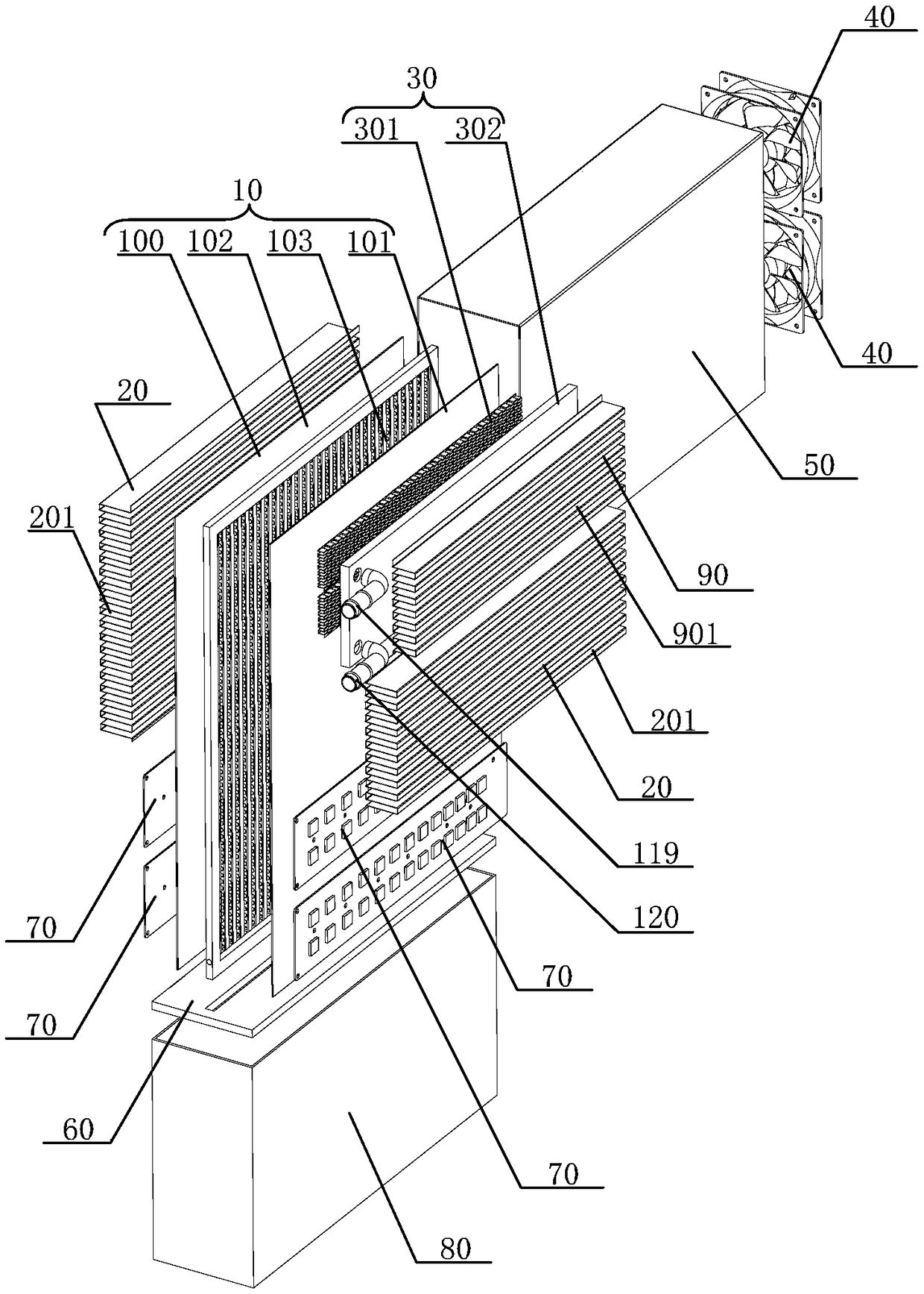
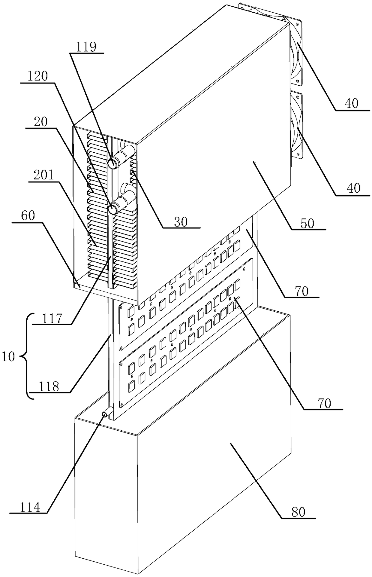
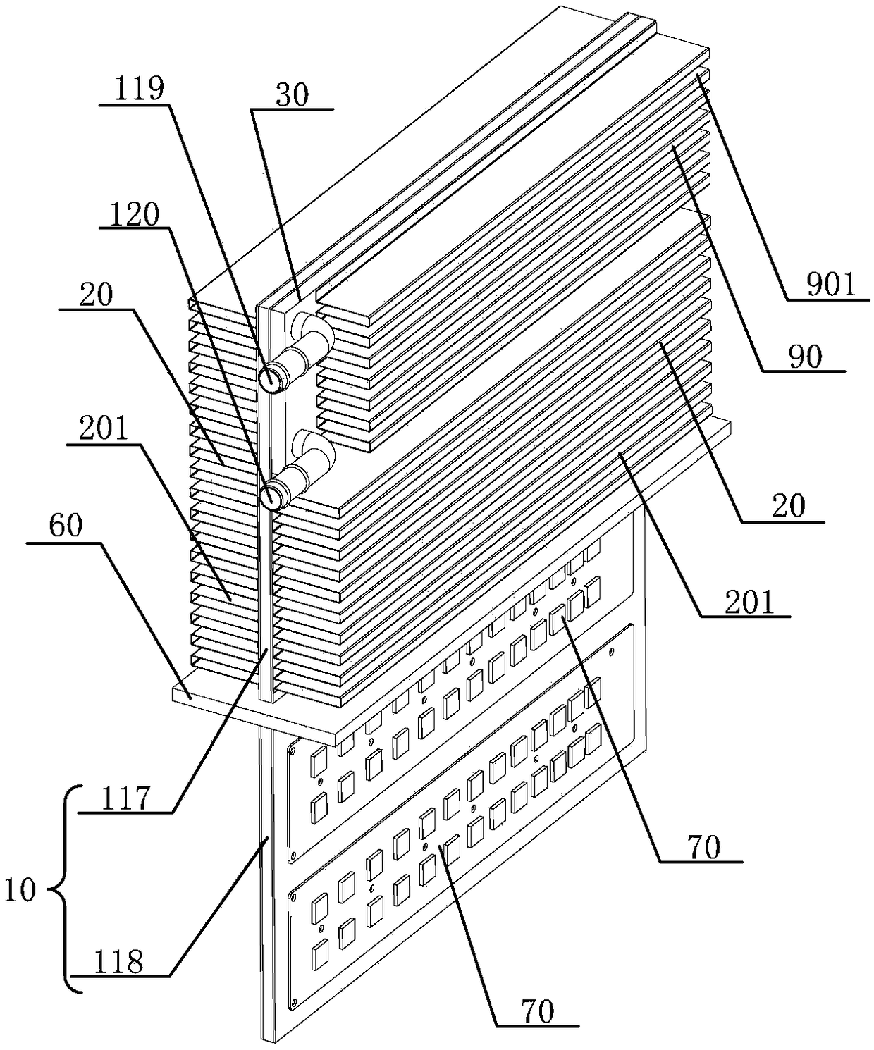
[0124] see Figure 1 to Figure 12 , the present invention provides an air-cooled and liquid-cooled combined thermal superconducting plate radiator, the air-cooled and liquid-cooled combined thermal superconducting plate radiator includes: a thermal superconducting plate 10, the thermal superconducting plate 10 is formed There are interconnected sealed passages 106, and the sealed passages 106 are filled with heat transfer working medium 1061; a liquid cooling radiator 30, the liquid cooling radiator 30 is located on the surface of the thermal superconducting plate 10, and the liquid cooling A liquid channel is formed in the radiator 30, and the liquid cooling radiator 30 is provided with a liquid inlet 3023 and a liquid outlet 3024 communicating with the liquid channel; the first cooling fin 20, the first cooling fin The sheet 20 is located on at least one surface of the thermal superconducting plate 10, and a plurality of first heat dissipation channels 201 arranged in parall...

Embodiment 2

[0152] Please combine Figure 1 to Figure 20 refer to Figure 21 to Figure 23 , this embodiment also provides an air-cooled and liquid-cooled combined thermal superconducting plate radiator, the structure of the air-cooled and liquid-cooled combined thermal superconducting plate radiator described in this embodiment is the same as that described in Embodiment 1 The structure of the air-cooled and liquid-cooled combined thermal superconducting plate radiator is roughly the same, the difference between the two is that the specific structure of the thermal superconducting plate 10 is different: the thermal superconducting plate 10 described in this embodiment is compared to the embodiment The thermal superconducting plate 10 described in Example 1 is provided with at least one reserved gap 1035 in the second deflector 103, and at the same time, the thermal superconducting plate 10 also includes at least one spacer 109 or the first At least one punching boss 113 is disposed on th...

Embodiment 3

[0157] Please combine Figure 1 to Figure 20 refer to Figure 24 to Figure 25, this embodiment also provides an air-cooled and liquid-cooled combined thermal superconducting plate radiator, the structure of the air-cooled and liquid-cooled combined thermal superconducting plate radiator described in this embodiment is the same as that described in Embodiment 1 The structure of the air-cooled and liquid-cooled combined thermal superconducting plate radiator is roughly the same, the difference between the two is that the structure of the thermal superconducting plate 10 is different: the thermal superconducting plate 10 described in the first embodiment The number of the two deflectors 103 is one, and the number of the second deflectors 103 described in this embodiment is at least two, and there is a gap between the adjacent second deflectors 103, so as to The first balance passage 107 of the heat transfer working medium 1061 is formed between the adjacent second guide plate 10...


PUM


Abstract

The invention provides an air-cooled liquid-cooled combined thermally superconducting plate type heat sink, comprising a thermally superconducting plate, a sealing passage formed in the thermally superconducting plate and communicated with each other, and a heat transfer working medium filled in the sealing passage; a liquid-cooled radiator located on the surface of the thermal superconducting plate, wherein a liquid passage is formed in the liquid-cooled radiator, and a liquid inlet port and a liquid outlet port communicated with the liquid passage are arranged on the liquid-cooled radiator;a first heat dissipation fin located on at least one surface of the thermal superconducting plate, wherein a plurality of first heat dissipation channels arranged in parallel spaces are formed in thefirst heat dissipation fin; at least one fan is position at one end of that first heat dissipation fin, and the air outlet surface of the fan faces the first heat dissipation fin and is perpendicularto the extending direction of the first heat dissipation passage. The invention has the following beneficial effects: the forced heat dissipation mode is flexible, the heat dissipation ability is remarkably enhanced, and another device can be used for forced heat dissipation when any device of air cooling or liquid cooling fails, which does not affect the heat dissipation effect, and has high reliability.

Description

technical field [0001] The invention belongs to the technical field of heat transfer, in particular to an air-cooled and liquid-cooled combined thermal superconducting plate radiator. Background technique [0002] With the rapid development of power electronics technology, the requirements for modularization, integration, light weight, low cost and high reliability are getting higher and higher, and the heat generated by power devices during operation is also increasing. Quickly dissipating the heat generated by the power device will cause the temperature of the chip in the power device to rise, which will cause a decrease in performance and shorten the service life, and will lead to the failure of the power device and the burning of the chip. Therefore, solving the heat dissipation problem of power devices has always been one of the core issues that plague power device packaging manufacturers and users. In order to effectively solve the heat dissipation problem of power de...

Claims


Application Information

Patent Timeline
Patent Type & Authority Applications(China)
IPC IPC(8): H01L23/473H01L23/467H01L23/427
CPCH01L23/427H01L23/467H01L23/473
Inventor 仝爱星唐必洪
Owner ZHEJIANG JIAXI TECH CO LTD
Why Eureka
Try Eureka