A wire-to-wire lightning circuit with a lower clamping voltage

A technology of clamping voltage and lightning protection circuit, which is applied in the field of LED power drive, can solve problems such as high residual voltage of the circuit, poor power supply lightning resistance, damage to LED drive power supply and lamp board, etc., to suppress transient surges and improve The effect of lightning resistance and low clamping voltage

Inactive Publication Date: 2019-01-11
惠州市华阳光电技术有限公司
View PDF3 Cites 1 Cited by
  • Summary
  • Abstract
  • Description
  • Claims
  • Application Information

AI Technical Summary

Problems solved by technology

[0005] The invention provides a line-to-line lightning protection circuit with lower clamping voltage. The technical problem to be solved is that in the existing LED power supply drive EMI circuit, a varistor with a slightly higher varistor voltage is placed at the front end of the common mode inductor, and a varistor with a slightly higher varistor voltage is placed at the rear. In the design of placing a varistor with a slightly lower varistor voltage at the terminal, when subjected to a transient current surge, because the clamping voltage of the two varistors rises synchronously, the lightning resistance of the power supply is poor, and here Under high clamping voltage, the residual voltage of the circuit is also relatively high, which may easily cause damage to the LED drive power supply and the lamp board

Method used


Image

  • A wire-to-wire lightning circuit with a lower clamping voltage

Examples


Embodiment Construction

[0012] The embodiment of the present invention will be explained in detail below in conjunction with the accompanying drawings. The examples given are only for the purpose of illustration, and cannot be interpreted as limiting the present invention. The accompanying drawings are only for reference and description, and do not constitute the scope of patent protection of the present invention. limitations, since many changes may be made in the invention without departing from the spirit and scope of the invention.

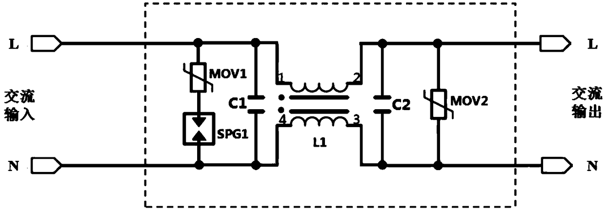
[0013] A line-to-line lightning protection circuit with a lower clamping voltage provided by an embodiment of the present invention, its electrical connection relationship is as follows figure 1 shown. In this embodiment, the line-to-line lightning protection circuit with lower clamping voltage is applied to LED power drive, and is specifically improved in the existing EMI circuit. The line-to-line lightning protection circuit of the embodiment of the present invent...


PUM


Abstract

The invention relates to the technical field of LED power supply driving, a wire-to-wire lightning protection circuit with low clamping voltage is disclosed. The circuit is provided with a first varistor, a second varistor, a common-mode inductor and a discharge tube, the first varistor being connected in series with the discharge tube between a fire line and a neutral line or between a fire lineand a fire line, and between a first homonymous terminal and a second homonymous terminal of the common-mode inductor, and the second varistor being connected between a first anonymous terminal and asecond anonymous terminal of the common-mode inductor, and the second varistor being connected between the first anonymous terminal and the second anonymous terminal of the common-mode inductor. The invention has the advantages that: When transient inrush currents occur, at this time, that clamp voltage after the conduction of both ends of the serie combined first varistor + discharge tube is substantially lower than the clamp voltage after the conduction of the second varistor. The clamping voltage of the present application is lower than a design in which a varistor is provided at the frontend of the common-mode inductor, which can suppress transient surge more effectively, improve lightning protection capability of the power supply, and achieve the purpose of more effectively protecting the power supply and the lamp board.

Description

technical field [0001] The invention relates to the technical field of LED power drive, in particular to a line-to-line lightning protection circuit with lower clamping voltage. Background technique [0002] According to ANSI / IEEEC62.41, which is the surge environment guideline for low-voltage (1000V and below) AC power circuits, the induced transient surge (Transients) in outdoor places (category C, entry point) will be as high as 15KA (6KV). Therefore, LED drivers for outdoor use generally place one or two Metal Oxide Varistors (Metal Oxide Varistors) in their EMI circuits as line-to-line lightning protection to protect the LED drivers and light boards. [0003] If two metal oxide varistors are used, the varistor voltage (Varistor Voltage) is generally placed slightly higher before the common mode inductor in the EMI (Electromagnetic Interference, literally translated as electromagnetic interference, in this application, representing anti-electromagnetic interference) circ...

Claims


Application Information

Patent Timeline
Patent Type & Authority Applications(China)
IPC IPC(8): H02H9/04H02H9/06
CPCH02H9/041H02H9/06
Inventor 陈伟健
Owner 惠州市华阳光电技术有限公司
Why Eureka
Try Eureka