
Composite insulator

A technology of composite insulators and insulating blocks, applied in the direction of insulators, supporting insulators, coatings, etc., can solve the problems of composite insulators such as easy damage, weak performance, short circuit, etc., to improve wind deflection resistance, enhance wind deflection resistance and lightning strike resistance performance effect

Active Publication Date: 2020-10-27
STATE GRID CORP OF CHINA +1
View PDF8 Cites 0 Cited by
  • Summary
  • Abstract
  • Description
  • Claims
  • Application Information

AI Technical Summary

Problems solved by technology

[0003] When the existing composite insulators are used, most of them choose among wind deflection protection, lightning protection or pollution flashover protection according to the characteristics of different regions, resulting in composite insulators with outstanding performance in only one aspect, and weak performance in other aspects
Therefore, composite insulators are easily damaged when used in complex environments, and have a low service life. At the same time, when used in harsh environments, it is very easy to cause problems such as short circuits

Method used


Image

  • Composite insulator
  • Composite insulator
  • Composite insulator

Examples


Embodiment 1

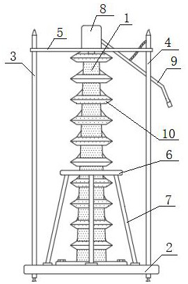
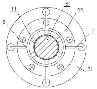
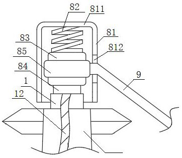
[0040] see Figure 1 to Figure 5 , a composite insulator, including a mandrel 1, six connecting columns 11 uniformly arranged around the circumference of the mandrel 1, a support seat assembly 2, No. 1 lightning arresters 3 and No. 2 arresters symmetrically arranged on the left and right sides of the mandrel 1 Lightning arrester 4, a conductive upper seat 8 located above the mandrel 1, and an arc striker 9. The support seat assembly 2 includes a base 21 and a support pad 22 embedded in the middle of the base 21. The upper surface of the base 21 is provided with There are multiple No. 2 arc spraying through holes 211, the lower end of the mandrel 1 is fixedly connected to the middle part of the support pad 22, the upper end of the mandrel 1 is connected with a transverse connecting rod 5, and the two ends of the transverse connecting rod 5 They are respectively fixedly connected to the upper ends of the No. 1 arrester 3 and the No. 2 arrester 4, and the lower ends of the No. 1 ...

Embodiment 2

[0042] The difference with Example 1 is:

[0043] The mandrel 1 is a tapered structure whose diameter gradually increases from top to bottom, and 10 sheds 10 are arranged on the mandrel 1 from top to bottom, and the outer walls of the mandrel 1 and sheds 10 are coated with Covered with an antifouling coating, the raw material composition and weight ratio of the antifouling coating are: silicone 30, polytetrafluoroethylene 22, fluorine-containing acrylic resin 30, crosslinking agent 25, organic fluoropolymer 17, Polyisocyanate 8, defoamer 7, surfactant 4, catalyst 3.


PUM


Abstract

The invention discloses a composite insulator, which comprises a core rod, a supporting seat assembly, a first lightning arrester and a second lightning arrester, wherein the first lightning arresterand the second lightning arrester are symmetrically arranged on two sides of the core rod, the lower ends of the core rod, the first lightning arrester and the second lightning arrester are fixedly connected with the supporting seat assembly; the upper end of the core rod is connected with a transverse connecting rod, the two ends of the transverse connecting rod are fixedly connected with the upper end of the first lightning arrester and the upper end of the second lightning arrester respectively, the middle of the core rod is sleeved with a supporting ring, the supporting ring is fixedly connected with the supporting seat assembly through a plurality of anchoring ropes evenly arranged around the periphery of the supporting ring, and the outer wall of the core rod is coated with an antifouling coating. The structure is excellent in windage yaw resistance, lightning stroke resistance and antifouling property.

Description

technical field [0001] The invention belongs to the technical field of electric equipment, and in particular relates to a composite insulator. Background technique [0002] An insulator is a device that can withstand voltage and mechanical stress installed between conductors of different potentials or between conductors and grounding members. There are many types of insulators with different shapes. Although the structures and shapes of different types of insulators are quite different, they are all composed of two parts: insulating parts and connecting fittings. With the change of atmospheric environment and the increasing severity of air pollution, natural disasters such as lightning strikes, pollution flashovers, wind deviation, and geological disasters directly threaten the operation safety of overhead transmission lines, which puts forward new requirements for the ability of overhead transmission lines to resist natural disasters . [0003] When the existing composite...

Claims


Application Information

Patent Timeline
IPC IPC(8): H01B17/14H01B17/38H01B17/46H01B17/50C09D183/04C09D133/00C09D127/18C09D5/08C09D5/16
CPCC08L2205/035C09D5/08C09D5/1675C09D133/00C09D183/04H01B17/145H01B17/38H01B17/46H01B17/50C08L33/00C08L27/18C08L83/04
Inventor 张雪霏李智威唐学军柯方超周秋鹏孙利平廖晓红贺兰菲高晓晶熊川羽王巍周蠡陈然姜山董弘川周英博马莉熊一明月张赵阳
Owner STATE GRID CORP OF CHINA
Learn More