
Movable bathtub assembly

A bathtub and component technology, applied in the field of movable bathtub components, can solve the problems of difficulty in cleaning the bathroom and occupying space.

Active Publication Date: 2019-01-11
SHUTEK FORVALTNING AB
View PDF14 Cites 5 Cited by
  • Summary
  • Abstract
  • Description
  • Claims
  • Application Information

AI Technical Summary

Problems solved by technology

To achieve this, we have to keep a stool in the bathroom, which takes up extra space
And keeping the bathroom clean is often difficult because some parts of the floor are inaccessible under the tub

Method used


Image

  • Movable bathtub assembly
  • Movable bathtub assembly
  • Movable bathtub assembly

Examples


Embodiment Construction

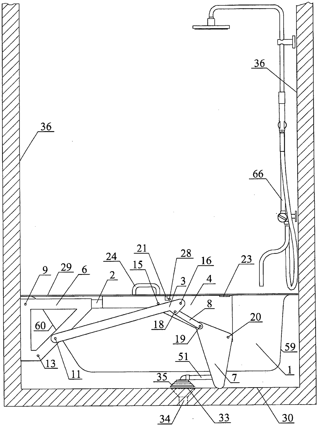
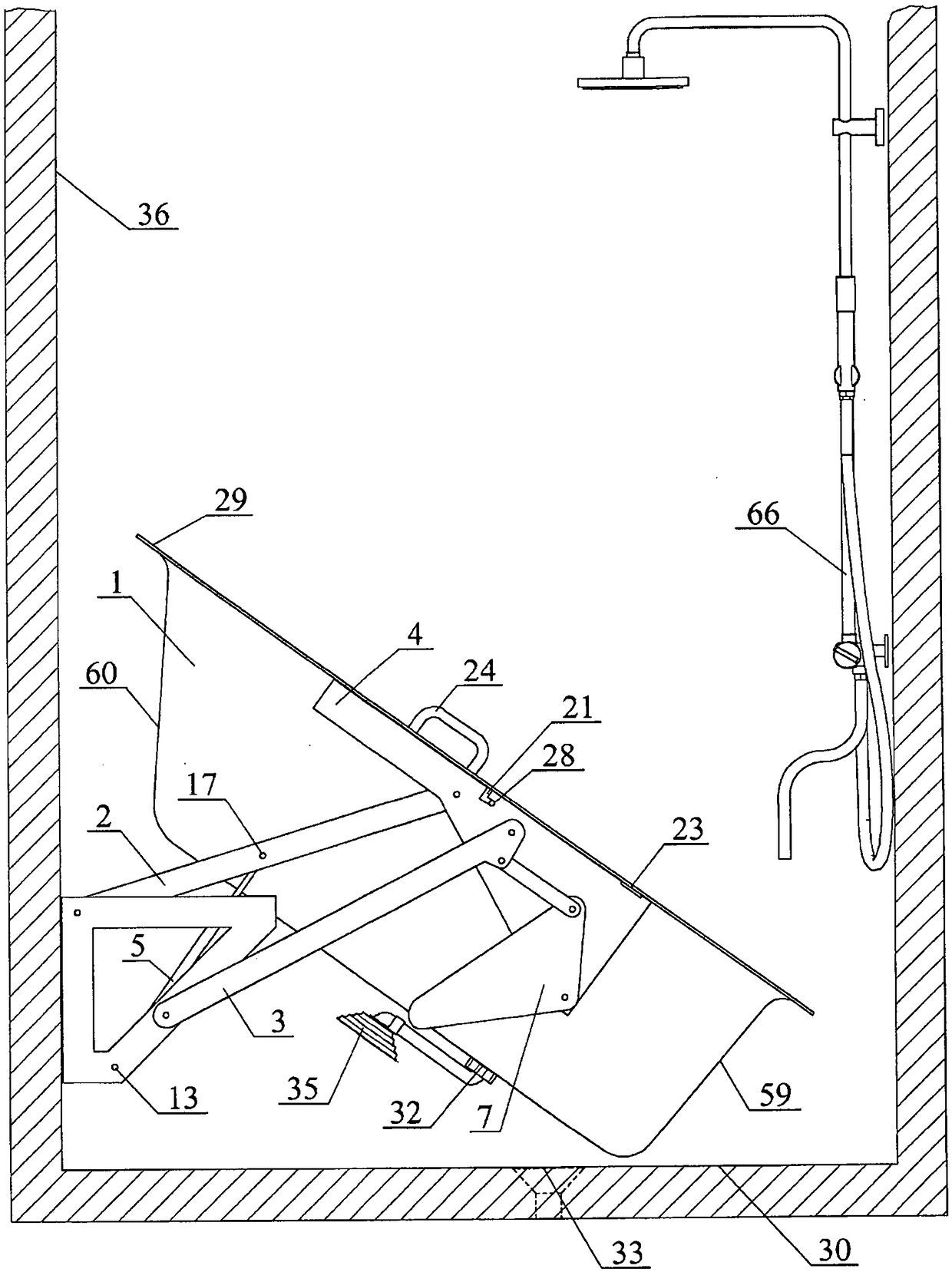
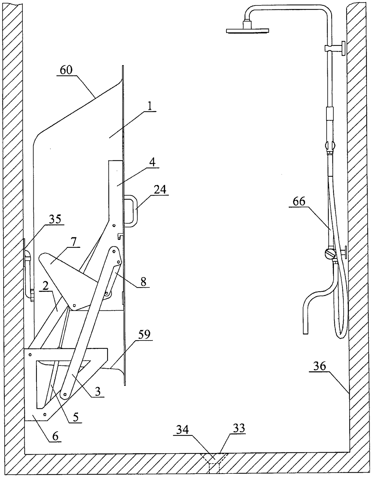
[0039] figure 1 Shown is a side view of the tub 1 assembly without fittings in a horizontal position, with uncovered four-bar linkage with swing linkage (rocker mechanism) and sewage removal system. figure 2 and image 3 The same tub assembly is shown in inverted and upright positions, respectively. figure 1 The tub 1 in is arranged relatively closely between the hypothetical walls 36 of the room equipped with the shower group 66 arranged on the wall above the side 59 of the tub 1 . The mechanism can be seen without the covers 52 and 53 covering it (see Figure 14 and Figure 15 ). It can be seen that the mechanism is in principle symmetrical on both sides of the bathtub 1 . This mechanism constituting a four-bar linkage is formed by a wall frame 6 connected by an articulated joint 9 to the front arm 2 and by an articulated joint 11 to the following arms 3 on both sides of the tub 1, while the two Each arm is connected to the bed-shaped part 4 of the bathtub 1 by means ...


PUM


Abstract

Movable bathtub assembly according to the present invention is characterised in that all arms, joints and mechanism mounting structures are arranged below an upper edge (29) of a bathtub (1) supportedby its legs (7) on a base (30) and situated in the bathing position, in principle horizontally, completely inside the space defined by the upper edge (29) of the bathtub (1), the base (30) and walls(36) adjusted to the bathtub (1), in such way, that the bathtub is displaced following the rotation of arms (2, 3) from its bathing position to its vertical position, where the concave side of the bathtub is directed towards the place of its centre in the bathing position.

Description

technical field [0001] The present invention relates to a portable bathtub assembly particularly suitable for use in private homes, rest homes and hospitals. Background technique [0002] Patent US535509A discloses a bathtub (also denoted by the letter "L") which is lifted into a wardrobe by a tether connected to a shorter tub wall with a more gentle slope and by vertical guides on its sides Internally, this vertical guide guides the tub L through movable joints fixed on the upper part of the tub. This movement is assisted by the counterweight of the tub secured at the other end of the tether that passes through pulleys in the upper portion of the inner wall of the wardrobe. With this method, the bathtub is arranged in the wardrobe with its concave surface facing the outside. The tub is provided with folding legs. [0003] Patent US760540A describes a bathtub which is manually lifted inside the cabinet using hinges fixed on the bottom of the tub (at the edge where it conn...

Claims


Application Information

Patent Timeline
Patent Type & Authority Applications(China)
IPC IPC(8): A47K3/20A47K3/02A47K3/16A47K3/00A61H33/00
CPCA47K3/20A61H33/00A47K3/06A47K3/122A47K3/007
Inventor J·祖特考斯基
Owner SHUTEK FORVALTNING AB
Learn More