A root canal length measuring method and a root canal length measuring instrument

A root canal length measurement and root canal technology, applied in medical science, dentistry, etc., can solve problems such as capacitance or resistance deviation, inconsistent test results, etc., and achieve consistent test results

Active Publication Date: 2019-01-15
汕尾市葆丰医疗器械有限公司
View PDF6 Cites 1 Cited by
  • Summary
  • Abstract
  • Description
  • Claims
  • Application Information

AI Technical Summary

Problems solved by technology

[0006] The purpose of the embodiments of the present invention is to provide a root canal length measuring method and a root canal length measuring instrument, which are used to solve the inconsistent test results caused by the capacitance or resistance deviation of the frequency selection circuit in different existing root canal length measuring instruments The problem

Method used


Image

  • A root canal length measuring method and a root canal length measuring instrument
  • A root canal length measuring method and a root canal length measuring instrument
  • A root canal length measuring method and a root canal length measuring instrument

Examples


Embodiment 1

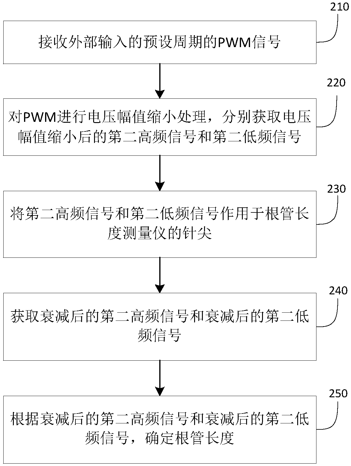
[0028] Embodiment 2 of the present invention provides a kind of root canal length measuring method, specifically as figure 2 as shown, figure 2 It is a schematic flowchart of a root canal length measurement method provided by an embodiment of the present invention. Primarily performed by a root canal length measuring instrument, the method may include:

[0029] Step 210, receiving a PWM signal with a preset period from an external input.

[0030] Specifically, an externally input PWM signal with a preset period. For example, it may be a PWM signal output through an IO port of a microcontroller. The signal is alternately composed of the first high-frequency signal of the first sub-period and the second low-frequency signal of the second sub-period. And the sum of the first sub-period and the second sub-period is exactly the preset period. For example, the preset cycle frequency is 8hz, and the cycle is 0.125s. The specific values ​​of the first sub-period and the second...

Embodiment 2

[0049] Corresponding to the above-mentioned embodiment 1, the embodiment of the present invention also provides a root canal length measuring instrument, specifically as Figure 5 as shown, Figure 5 A schematic diagram of the structure of the root canal length measuring instrument provided in this embodiment. Specific as Figure 5 As shown, the root canal length measuring instrument specifically includes: a receiving device 10 and a signal processing device 20 .

[0050] Wherein, the receiving device 10 is used to receive a PWM signal of a preset period input from the outside, and the PWM signal is alternately composed of a first high-frequency signal of a first sub-period and a second low-frequency signal of a second sub-period, the first sub-period and the second low-frequency signal of a second sub-period The sum of the second sub-period is the preset period;

[0051] The signal processing device 20 is configured to perform voltage amplitude reduction processing on the ...


PUM


Abstract

The invention discloses a root canal length measuring method and a root canal length measuring instrument. The method is carried out by the root canal length measuring instrument. The method comprisesthe following steps: receiving a preset period PWM signal inputted from the outside; alternately forming a first high frequency signal with a first sub-period and a second low frequency signal with asecond sub-period; performing voltage amplitude reduction processing on the pwm to respectively obtain a second high frequency signal and a second low frequency signal after the voltage amplitude reduction; applying a second high frequency signal and a second low frequency signal to the tip of the root canal length measuring instrument; acquiring the attenuated second high frequency signal and the attenuated second low frequency signal; determining the root canal length based on the attenuated second high frequency signal and the attenuated second low frequency signal. The method and the instrument can skillfully avoid the influence of the deviation of the hardware parameters on the voltage amplitude when the frequency selection circuit is used, and then the influence on the test results.So that the results of root canal length tester produced by the manufacturer can be consistent.

Description

technical field [0001] The invention relates to the technical field of electronic measurement, in particular to a root canal length measuring method and a root canal length measuring instrument. Background technique [0002] The root canal length measuring instrument, referred to as the root measuring instrument, is a precision electronic instrument used to measure the working length of the root canal. Through the guidance of the root tester, compared with the traditional root canal length x-ray measurement method, the accuracy can be higher, so that doctors can accurately grasp the root canal length to achieve perfect filling. [0003] Most of the current root canal measurements are based on the impedance principle. That is, in 1958, Sunada found that the resistance value between the human periodontal ligament and the oral mucosa was constant, about 6.5k ohms, and was used to measure the working length of the root canal. But in the actual test process, it will be found th...

Claims


Application Information

Patent Timeline
Patent Type & Authority Applications(China)
IPC IPC(8): A61C19/04
CPCA61C19/041
Inventor 施程峰
Owner 汕尾市葆丰医疗器械有限公司
Why Eureka
Try Eureka