
Steel bar bending device for engineering construction

A technology for engineering construction and bending device, applied in the field of engineering construction, can solve the problems of side slip between the device and the ground, large bending force, large bending range of steel bars, etc., so as to facilitate fixing, increase contact area, and increase friction force effect

Inactive Publication Date: 2019-01-15
王晓霞
View PDF9 Cites 0 Cited by
  • Summary
  • Abstract
  • Description
  • Claims
  • Application Information

AI Technical Summary

Problems solved by technology

The above-mentioned patents have the following deficiencies: 1. When the steel bar is bent, it is necessary to fix the steel bar to prevent the steel bar from falling off from the device during bending and causing accidental injury to the operator; 2. When the steel bar is bent, due to Vibration will occur during the bending process, which will cause side slip between the device and the ground, which will affect the bending treatment of the steel bar by the device; 3. When bending the steel bar, due to the large bending force of the device, the steel bar may be The bending range is large and the fracture

Method used


Image

  • Steel bar bending device for engineering construction
  • Steel bar bending device for engineering construction
  • Steel bar bending device for engineering construction

Examples


Embodiment Construction

[0027] The technical solutions in the embodiments of the present invention will be clearly and completely described below in conjunction with the accompanying drawings in the embodiments of the present invention. Obviously, the described embodiments are only a part of the embodiments of the present invention, rather than all the embodiments.

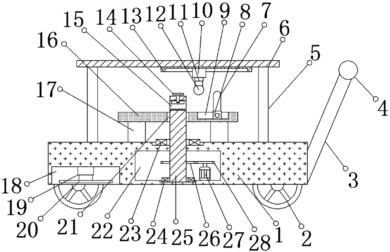
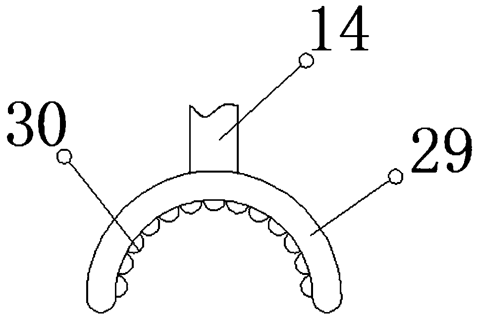
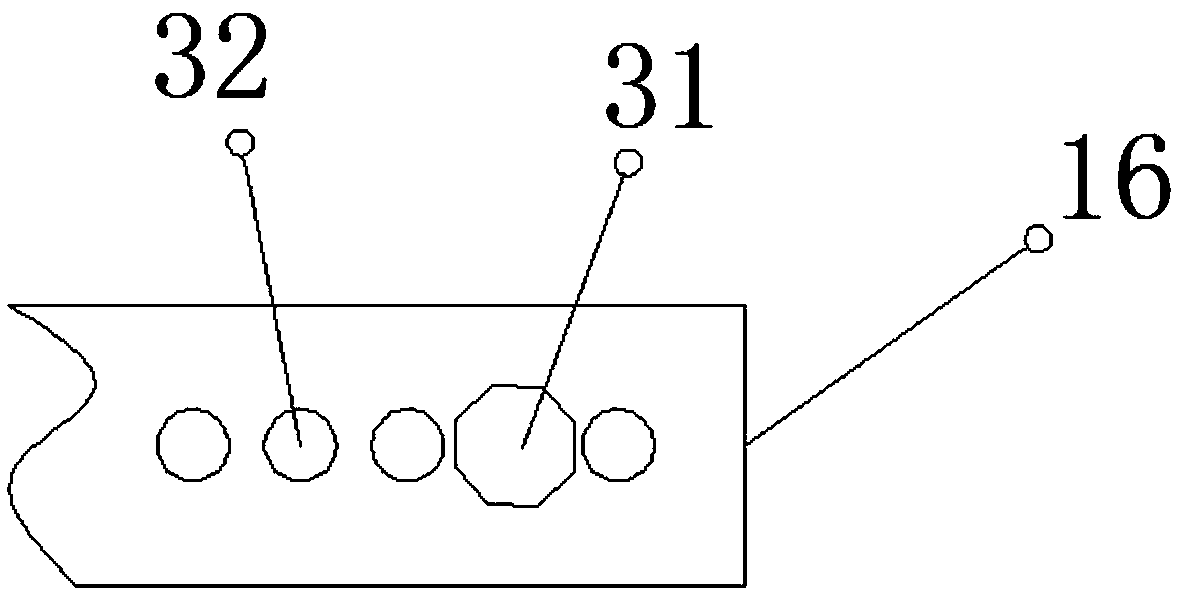
[0028] Reference Figure 1-5 , A steel bending device for engineering construction, comprising a bottom plate 1, the outer walls of both sides of the bottom plate 1 are rotatably connected with moving wheels 2, and the number of moving wheels 2 is four, and both sides of one side of the bottom plate 1 are welded There is a fixed rod 3, and a reinforcing rod 33 is welded on the outer wall of one side of the two fixed rods 3 near the middle. The outer wall of the two fixed rods 3 is connected with a push rod 4 by bolts on the side away from the bottom plate 1, and the push rod A protective sleeve 34 is sleeved on the outer wall of the protect...


PUM


Abstract

The invention discloses a steel bar bending device for engineering construction. The steel bar bending device comprises a bottom plate. The outer walls of the two sides of the bottom plate are connected with moving wheels in a rotating mode, and the number of the moving wheels is four. Fixed rods are arranged on the two sides of the outer wall of one side of the bottom plate. A reinforced rod is arranged at the positions, close to the middle, of the outer walls of one sides of the two fixed rods. A pushing rod is arranged on one sides, away from the bottom plate, of the outer walls of the twofixed rods. The outer wall of the pushing rod is connected with a protective sleeve in a sleeved mode. Protrusions which are distributed at equal intervals are arranged on the outer wall of the protective sleeve. A controller is arranged on one side of the outer wall of the top of the pushing rod. Supporting rods are connected to the two sides of the outer wall of the top of the bottom plate through bolts. According to the invention, steel bars can be prevented from falling off the device during the bending process of steel bars. Meanwhile, the device is prevented from sliding laterally on theground due to the vibration of the device during the working process of the device. The breakage of steel bars, due to the large bending amplitude of the steel bars under the large bending force of the device during the steel bar bending process, can be avoided.

Description

Technical field [0001] The invention relates to the technical field of engineering construction, in particular to a steel bar bending device for engineering construction. Background technique [0002] At present, steel bars are widely used in engineering construction. When steel bars are used, they are usually bent to meet the needs of construction. However, because the steel bars are not easy to be bent, they need to be bent by a bending device. Bending treatment. [0003] After searching, the Chinese patent grant number CN207655793U discloses an efficient steel bending device in the field of construction engineering, including a bottom plate, a driving device located above the bottom plate, and a positioning device provided on the left side of the driving device The lifting device located above the driving device and the pushing device provided on the lifting device are characterized in that: the bottom plate is provided with a plurality of universal wheels located below it, a f...

Claims


Application Information

Patent Timeline
Patent Type & Authority Applications(China)
IPC IPC(8): B21F1/00
Inventor 王晓霞吴晓东蒋占明孙湘闻利王晓龙
Owner 王晓霞
Learn More